If the power supply is putting out 9.1 volts, the resistor value is a bit low.
A resistor in the range of 820 ohms to 1k ohms would probably be better.
A resistor in the range of 820 ohms to 1k ohms would probably be better.
Measure the voltage of the power supply before you install the LED.
Make sure that the relay coil is in the circuit or the voltage will be very high.
What is the d.c. resistance and operating voltage of the relay coil? That will determine the resistance of R1 and R2.
I'm guessing that 20k is too much resistance for the LED.
Make sure that the relay coil is in the circuit or the voltage will be very high.
What is the d.c. resistance and operating voltage of the relay coil? That will determine the resistance of R1 and R2.
I'm guessing that 20k is too much resistance for the LED.
Hi Frank
Below is the spec:
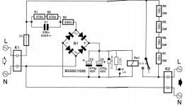
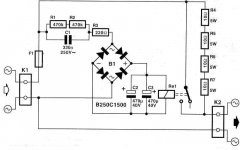
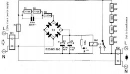
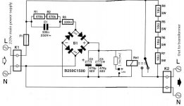
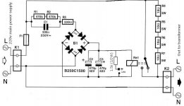
R1, R2*.............................470K 0.25W 1% mf
R3*..................................220R 0.25W 1% mf
R4, R5, R6, R7...................10R 5W
C1...................................330n 250V (for direct mains connection)
C2, C3............................. 470uF 40V
B1.................................. B250C1500
Re1.................................24V (250V-8A contact)
F1*..................................2A slow blow
I've simulated the circuit. Depending on the relay coil resistance, you may need to trim R1 and/or R2 to obtain something near 24 volts on the relay coil.
The resistor feeding the LED should be about 1.2k/1.5k.
A .25 or .5 watt resistor is good.
The resistor feeding the LED should be about 1.2k/1.5k.
A .25 or .5 watt resistor is good.
Hi Frank
Thanks again. I'll change it to 1.5k 5w. What value is suitable for R1 and R2? The mains is at between 220-230v. I have connect a voltage regulator which will output at close to 240v to the soft start.
Thanks again. I'll change it to 1.5k 5w. What value is suitable for R1 and R2? The mains is at between 220-230v. I have connect a voltage regulator which will output at close to 240v to the soft start.
Attachments
Last edited:
Don't need a 5 watt resistor. .5 (1/2) watt is big enough.
The value of R1 and R2 depends on the coil resistance of the relay.
Increasing the value of C1 will also increase the voltage to the relay coil.
Experiment with the values to obtain something near 24 volts on the relay coil.
The value of R1 and R2 depends on the coil resistance of the relay.
Increasing the value of C1 will also increase the voltage to the relay coil.
Experiment with the values to obtain something near 24 volts on the relay coil.
I am interested to know much limitation do these resistors provide before the load is connected by relay.
I am interested to know much limitation do these resistors provide before the load is connected by relay.
That would depend upon the amount of current being drawn by the load through the resistors.
I see, then we have to calculate the bypass resistors values before we use the circuit because resistors might end up flamed if wrong values used. For a transformer, the power rating is enough to be used for these calculations?
Also what happens if I use 1000uF/50V capacitor instead of two 470uF/40V capacitors?
Also what happens if I use 1000uF/50V capacitor instead of two 470uF/40V capacitors?
It doesn't work with the zener and 1.5k resistor in. How much do i need to trim on R1 and R2?
Last edited:
Pm,
be very careful with this circuit.
It is connected directly to the mains.
Don't touch any parts while it is plugged into the mains supply.
The 470k+470k do not supply much current.
If your mains is 230Vac and you use 24V for the relay drive, you have 215Vac to drive current through the 940k, I=V/R = ~0.23mA
The main current to drive the circuit comes through the capacitor, it must be X rated.
Find their AC impedance at your mains frequency and using the same formula find out how much AC current passes the capacitor.
Is that sufficient to drive the LED and to drive the relay?
You'll need the zener only when you have the circuit unloaded.Add 24v ZANER DIODE to control the voltage constant.
What you should do in order to have a LED is simply to insert it and put 47-100 ohms across it in order to modify the current through the LED.
You can read more about it here and download schematics.
MLD01 Mains LED driver - Schematic description
SST02 Softstart for toroid transformers
- Status
- Not open for further replies.
- Home
- Amplifiers
- Power Supplies
- soft start help
