by far the better way to discharge capacitors.I would use one or more of the "normally off" contacts to discharge the PS caps through a resistor.
I looked at using a cascade of small bulbs to give a variable resistor to help reduce the drain on the PSU with a permanently connected discharge route.
With +-58.5Vdc and a series string of 5off 12V bulbs on each polarity.
When the amplifier is fully up to operating voltage the filaments are hot and high resistance, drawing minimal current from the PSU.
As the voltage drops at turn off, the bulbs cool to a bright glow and start to draw more current than the hot filament resistance would pass.
Gradually the PSU voltage becomes so low that the filaments are near their cold temperature resistance values and they draw down the last few volts fairly quickly.
It works, but not very well. The problem is the roughly 3:1 ratio of hot:cold resistance. If filaments had a 10:1 hot:cold resistance, this variable resistance discharger would work much more efficiently.
This is a sort of constant current discharge circuit.
Last edited:
I managed to locate a paper that relates thermistor soft turn-on to valve heater warm up - which was of interest to my present project, but maybe not this thread so much - however it is quite interesting as the application is for early valve computers.
http://dalmura.com.au/projects/Thermistors for the gradual application of heater voltage.pdf
Ciao, Tim
http://dalmura.com.au/projects/Thermistors for the gradual application of heater voltage.pdf
Ciao, Tim
NTC will not only reduce inrush current but also acts as a snubber across the relay contacts when they open. Hence contacts will not arc. Here is a picture of an NTC that use with 1000VA toroidal products and comes in boxes of 3000 at an equivalent price of US$ 0.38
I cannot see the manufacturer emblem properly but we purchase it from AVNET.
These things have been in our products for more that past 40 years and I have not had reports of any failing in the field.
I cannot see the manufacturer emblem properly but we purchase it from AVNET.
These things have been in our products for more that past 40 years and I have not had reports of any failing in the field.

Hi Nico,
Maybe you could describe where the relay contacts are in your circuit, because in the general circuit described in this thread I think you will find that that there is no way for an arc to develop across those contacts.
An arc could develop across the main incoming AC power switch when it is opened, which is why it would be good to have an RC snubber across the transformer primary, or alternatively a MOV.
Ciao, Tim
Same Topic, but other Headline: "Inrush Current Limiter"
check out this thread:
http://www.diyaudio.com/forums/pass...ter-solution-large-toroidal-transformers.html
In this case also this threads could be of interest:
Inrush Current (Soft Start), Transformer-Buzzing through DC, Power Supply
http://www.diyaudio.com/forums/power-supplies/152527-large-capacitors-inruish-current.html
http://www.diyaudio.com/forums/solid-state/157367-soft-start-headache.html
http://www.diyaudio.com/forums/parts/160969-external-ps-source.html
http://www.diyaudio.com/forums/soli...nt-limiter-their-amplifiers-very-special.html
http://www.diyaudio.com/forums/everything-else/6692-buzzing-toroid-transformer.html
http://www.diyaudio.com/forums/solid-state/162168-fast-rectifiers-power-supplies.html
http://www.diyaudio.com/forums/soli...t-buzzing-toroid-transformers-what-right.html
http://www.diyaudio.com/forums/solid-state/163889-can-toroidal-transformer-produce-all-mess.html
http://www.diyaudio.com/forums/solid-state/2080-dc-filter.html
http://www.diyaudio.com/forums/solid-state/37942-diy-ps-audio-humbuster.html
Hi Nico,
Maybe you could describe where the relay contacts are in your circuit, because in the general circuit described in this thread I think you will find that that there is no way for an arc to develop across those contacts.
An arc could develop across the main incoming AC power switch when it is opened, which is why it would be good to have an RC snubber across the transformer primary, or alternatively a MOV.
Ciao, Tim
Hi Tim,
I use two NTC across two poles of a double pole OMRON 230VAC (soft start) relay, in series before this delayed relay is the power relay, which is a similar relay that is used to turn the amp on and off.
The reason for the double power relays are because the power amp is turned on and off by a momentary push button at low voltage.
When the push button is pressed a PIC controls both relays via zero crossing opto coupler. The main relay is turned on first followed by 500 mS dealy then operates the soft start relay which by-passes the NTCs and applies full power to the transformer.
While power is applied in the turn-on state both relay contacts are protected by the NTC.
When power is turned off the soft start relay is dropped out 200 mS before the main relay and again the NTC protects its contacts from arcing when opening. The mains relay has a normal snubber of 150 ohms in series with 47 nF.
Regards
Nico
Hi Nico - interesting! A few comments - if you don't mind.
Have you checked when the main relay contacts first touch - compared to zero crossing? You may find that circuit delays, etc, and the actual voltage at the time, can minimise initial magnetising in-rush level - which you may be able to minimise through a programmed delay.
You indicate that the main relay contacts are snubbered - is the snubber across the relay contact (ie. bridging the isolation switch), or between active and neutral on the the amp side?
Ciao, Tim
Hi Nico - interesting! A few comments - if you don't mind.
Have you checked when the main relay contacts first touch - compared to zero crossing? You may find that circuit delays, etc, and the actual voltage at the time, can minimise initial magnetising in-rush level - which you may be able to minimise through a programmed delay.
You indicate that the main relay contacts are snubbered - is the snubber across the relay contact (ie. bridging the isolation switch), or between active and neutral on the the amp side?
Ciao, Tim
Hi Tim,
the snubber is across the mains connect/disconnect relay contacts in other word is for the purpose of snubbing the initial current when the contacts are starting to open and this is when contacts arc.
The NTC is across the contacts on the inrush current limiter, and when these contacts open the NTC takes the current away from the opening contacts.
Snubbing contacts is a common practise to protect contact arc in industry, you just need to calculate the resistance capacitance value to quench the spark at the instant of opening in worst case conditions normally associated with inductive loads.
Normally contacts do not arc on closing since we are operating a relatively low voltage around 625V peak to peak, it is when they open and current continues to flow while they are drawing appart and then pit the contacts.
The zero crossing couplers have no real value here since the relay takes time to operate, why they were there was that I used to do soft starting by ramping the voltage using triacs, but triac plays havoc with the transformer load and was not a successful idea.
Placing snubber across the Live and Neutral has no effect other than being a load. Increasing the capacitance to such an extent to match the inductive load, then it is power factor correcting and the load will appear resistive, but won't protect the switch contacts.
Just a matter of interest, there is no purpose for the common 10 ohm 100nF capacitor combination placed across the output of an amp. what is it trying to make look like a resistive network, the tweeter. Which one?
Ciao Nico
Last edited:
- Status
- Not open for further replies.
- Home
- Amplifiers
- Solid State
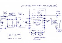
- SOFT START FOR POWER AMPS