i was recently on another forum, helping somebody sort out why it would be a good or bad idea to limit the current (on the power supply side) to the output transistors of an amplifier. and noted a curious side effect of using constant current sources to feed Vcc to the output devices. the output stage goes into soft clipping much like a tube amp (of course at reduced power). this could be an interesting "feature" for a guitar amp. anybody got any thoughts on this?
Soft clipping is seen in tube amps because the power tubes have significant plate voltage (50V to 100V) when they reach maximum current. They can put more voltage to the load if they don't have to supply more current. A speaker allows this because current and voltage are not in phase at most frequencies. This is the phenomenon know as "tube watts", a 100W tube amp can supply more voltage to a speaker than a 100W transistor amp. You don't see soft clipping when you are connected to a resistive load.
Limiting the current that a transistor amp can supply to a speaker is part of the solution. If you limit current at the supply, you must make sure that the rest of the amp does not suffer when the voltage collapses under current limit. Most transistor amps have circuitry to limit dissipation in the output devices. That would be a better place to limit the current. It could be as simple as increasing the emitter resistors that are usually used to sense the current. Typically something like 0.33 ohm at 5 watts, install a switch to change them to 1 ohm 10 watt. Some dissipation limiting circuits sound terrible when they are tripped. Maybe just stick the resistors in series with the collectors and short them out with a switch.
Limiting the current that a transistor amp can supply to a speaker is part of the solution. If you limit current at the supply, you must make sure that the rest of the amp does not suffer when the voltage collapses under current limit. Most transistor amps have circuitry to limit dissipation in the output devices. That would be a better place to limit the current. It could be as simple as increasing the emitter resistors that are usually used to sense the current. Typically something like 0.33 ohm at 5 watts, install a switch to change them to 1 ohm 10 watt. Some dissipation limiting circuits sound terrible when they are tripped. Maybe just stick the resistors in series with the collectors and short them out with a switch.
Tubes clip softer because of the circuit they are in rather than the voltage. Take a tube amp with a lot of negative feedback (NFB) and it will clip as hard as a transistor amp. It does not matter if you have a resistive or a partially reactive load. The tube amp can supply more voltage into the reactive ranges of a speaker if it is running as a pentode which has a high internal resistance. It acts as a constant current source and will adjust the voltage as high as need be to push the current through the load. Because the impedance at the load is higher the current is less. It is not so much that the tubes are putting out more power but rather that they are putting out a constant power rather than an amp that has a low impedance and puts out the same voltage no matter what the load impedance. A tube amp with a low output impedance, say a triode amp or one with NFB will not have the increased power delivery where the impedance of the speaker rises. I built an amp that has a switch to switch in and out the NFB and you can hear the increased output in the bass and treble with it switched out. With it switched in the speaker sounds more flat.
This is much different than amplifier sag. That is when there is resistance in the power supply and when the amplifier draws more current there is a voltage drop to the amplifier. The amp will clip just as hard (or soft) as it did at the higher voltage but it will do it at a lower voltage under a sustained signal. Some newer guitar amps do run in more of a constant current mode but that is more to decrease the dampening of the amp. This gives the same rise in output as the impedance of the speaker rises as with the tube amp. Again NFB is an important parameter in the effectiveness of the concept. There is much more involved than my two cent tour. I am just generalizing and just scratching the surface. It is easier to build a higher powered amp and modify the signal before it gets in the amp to have a soft clip and then keep the amp from entering hard clipping.
This is much different than amplifier sag. That is when there is resistance in the power supply and when the amplifier draws more current there is a voltage drop to the amplifier. The amp will clip just as hard (or soft) as it did at the higher voltage but it will do it at a lower voltage under a sustained signal. Some newer guitar amps do run in more of a constant current mode but that is more to decrease the dampening of the amp. This gives the same rise in output as the impedance of the speaker rises as with the tube amp. Again NFB is an important parameter in the effectiveness of the concept. There is much more involved than my two cent tour. I am just generalizing and just scratching the surface. It is easier to build a higher powered amp and modify the signal before it gets in the amp to have a soft clip and then keep the amp from entering hard clipping.
The oscilloscope picture below was taken by inserting a 0.05 ohm resistor in the ground leg of the output transformer of a Fender 5F6A re-issue. A scope probe monitors the voltage across the resistor and sends that to the scope vertical. The deflection factor is 4 amps per division. The horizontal measures the voltage across the 2 ohm nominal speaker load at 5 volts per division. Zero volts at zero amps is in the center of the screen.
The white line is a 2 ohm resistive load line. Note that 50W at 2 ohms is 14.14V peak, 7.07 amps peak. The red triangles are where the amp can supply more voltage than needed for 50W into 2 ohms. Those are your "Tube watts" where the tube amp applys more voltage to the speaker than a solid state amp of the same power rating or clipping level.
A Gibson SG was played through the amp at fairly high volume. Compare to AC/DC's "You Shook Me All Night Long". The scope is a Tektronix 7104 with fairly long display persistance. At times (not shown) you can see inductive spikes create voltages at the speaker that are well off screen horizontally. These are where the plate voltage goes negative on one output tube while the other tube sees several thousand volts.
If you don't believe in Tube watts, hook a scope to the output of a tube amp. Connect an A/B toggle switch to select a resistive load or a speaker of the same nominal impedance. Now play a guitar through the amp and notice how more voltage is applied to the speaker than the resistive load.
Attachments
If you don't believe in Tube watts, hook a scope to the output of a tube amp. Connect an A/B toggle switch to select a resistive load or a speaker of the same nominal impedance. Now play a guitar through the amp and notice how more voltage is applied to the speaker than the resistive load.
I take it you were disappointing in my answer. Well I am too terribly impressed with your post above.
Soft clipping is seen in tube amps because the power tubes have significant plate voltage (50V to 100V) when they reach maximum current.
Which means what? Reading it now it seems that you might be missing a word or two, possibly?
Soft clipping is seen in tube amps because the power tubes have significant plate voltage (50V to 100V) across them when they reach maximum current.
Which would make more sense to me but I still do not agree that is what makes a tube clip softer.
They can put more voltage to the load if they don't have to supply more current. A speaker allows this because current and voltage are not in phase at most frequencies.
I would not have minded a bit on explaning that this is where the speaker has a higher impedance. Now the speaker causes the voltage and the current to be a little out of phase in the mid band, where the impedance of the speaker is close to its rated ohms value, and to a greater extent at the resonance frequency and in the upper registers where the impedance of the speaker climes. I am of the opinion that the bulk of the speaker's impedance is close to its rated impedance.
http://www.eminence.com/pdf/Legend_1258.pdf
This is the phenomenon know as "tube watts", a 100W tube amp can supply more voltage to a speaker than a 100W transistor amp. You don't see soft clipping when you are connected to a resistive load.
A tube amp can supply more voltage to a speaker than a solid state amp where the speaker deviates appreciably from its 8 ohm spec. (let us assume the speaker is an 8 ohm speaker), and as long as the amp is designed with the intent to keep the output impedance low. There are new SS amp designs where the internal impedance is kept higher in order to give more of a tube amp feel. I will not be searching for examples, if you are interested check out the SS amp threads in tdpri.com.
As far as tube amps not soft clipping into a resistive load, are you sure? I have seen it when I was experimenting on my amps. Also a tube amp with a greater amount of negative feedback will clip harder than one without. But I did say that in my previous post. I also said that a tube amp can deliver more power 'where the impedance of the load is higher' than a SS amp. I would not call that 'tube watts' as you end up with uninformed musicians thinking that one watt of energy out of a tube amp is more powerful than one watt of energy out of a SS amp. And that is not the case.
One amp may be able to deliver more power than the other but that is not necessarily due to the use of tubes or transistors but in the design of the amp. Also amps with triodes (although rare in guitar amps, usually with pentode amps that have a low power mode, or some of the micro powered amps that utilize 12AU7's or the like) are designed with a lower plate impedance rather than a high one as with pentodes. These amps, or modes of operation, cause the amp to act more as a SS amp, namely the output voltage remains more constant in relation to the speaker impedance. And when the voltage remains more constant and the impedance rises you get less 'tube watts' and just the regular watts that a SS amp (non-tube amp simulated design) would put out.
Which all does not cause soft clipping.
Hope you do not take offense in my reply, I have enjoyed reading some of your posts on other sites and probably will continue to do so.
Tubes clip softer because of the circuit they are in rather than the voltage. Take a tube amp with a lot of negative feedback (NFB) and it will clip as hard as a transistor amp. It does not matter if you have a resistive or a partially reactive load.
I agree that the amount of feedback influences how hard an amp clips, but having a reactive load plays a big role. You have probably never fed sine waves to an amp at clipping with a speaker connected. Use ear plugs!
The high internal resistance of a tetrode or pentode is negated by negative feedback. Even without feedback, an output tube is not in a high impedance state when clipping as it runs up and down the vertical portion of the plate curves. If you look at the X-Y graph I posted, you see the slanted lines in the triangle regions. If you calculate the resistance of those lines, it's about 0.8 or 0.9 ohms. That is significant for an amp driving a 2 ohm load. The bluryness of those the lines is caused by power supply ripple.The tube amp can supply more voltage into the reactive ranges of a speaker if it is running as a pentode which has a high internal resistance. It acts as a constant current source and will adjust the voltage as high as need be to push the current through the load.
No amp delivers more power when the impedance rises. The whole idea of "constant power" is a generalization given as an explanation to non-technical people.It is not so much that the tubes are putting out more power but rather that they are putting out a constant power rather than an amp that has a low impedance and puts out the same voltage no matter what the load impedance. A tube amp with a low output impedance, say a triode amp or one with NFB will not have the increased power delivery where the impedance of the speaker rises.
Negative feedback reduces output impedance. Removing negative feedback increases output impedance which emphasizes frequencies where the impedance of a speaker is higher.I built an amp that has a switch to switch in and out the NFB and you can hear the increased output in the bass and treble with it switched out. With it switched in the speaker sounds more flat.
This makes me wonder if the OP has the same definition of "soft clipping" as you and I do. Did he mistake sag for soft clipping? Does he even own an oscilloscope?This is much different than amplifier sag. That is when there is resistance in the power supply and when the amplifier draws more current there is a voltage drop to the amplifier.
Which means what? Reading it now it seems that you might be missing a word or two, possibly?
Plate voltage is the voltage at the plate of a tube. Since the cathode of most power tubes is grounded, where else would the voltage be except across the tube?
I would not have minded a bit on explaning that this is where the speaker has a higher impedance. Now the speaker causes the voltage and the current to be a little out of phase in the mid band, where the impedance of the speaker is close to its rated ohms value, and to a greater extent at the resonance frequency and in the upper registers where the impedance of the speaker climes. I am of the opinion that the bulk of the speaker's impedance is close to its rated impedance.
http://www.eminence.com/pdf/Legend_1258.pdf
A guitar amp when clipping contains a broad range of frequencies. As seen in the picture I posted of a power cord, a large portion of the voltage and current are in the upper left and lower right quadrants. In those quadrants, the current is flowing the wrong way because of the reactive load. In fact it is pretty hard to play any notes on a guitar (beyond the clipping point) that do not cross those quadrants over part of the wave.
A tube amp can supply more voltage to a speaker than a solid state amp where the speaker deviates appreciably from its 8 ohm spec. (let us assume the speaker is an 8 ohm speaker), and as long as the amp is designed with the intent to keep the output impedance low. There are new SS amp designs where the internal impedance is kept higher in order to give more of a tube amp feel. I will not be searching for examples, if you are interested check out the SS amp threads in tdpri.com.
I would think those amps clip pretty hard. The current sense resistor is usually about 0.22 ohms. When the output hits the rail, the impedance is pretty low. I haven't experimented with this yet. What I want to try is this: Take a solid state amp, with or without mixed mode feedback (that's what Teemu Kyttala calls it, see his book). Install a resistor between the output of the amp and the speaker jack. Make it about 1/4 to 1/3 the intended load impedance. Next, double the value of the feedback resistor that goes between the output (before the new series resistor) and the inverting input to the power amp. Now install a new feedback resistor (same value as the other feedback resistor) from the speaker jack to the inverting input so as to keep the voltage gain close to the same. The power as measured with a dummy load will be lower, but will it sound more like a tube amp?
As far as tube amps not soft clipping into a resistive load, are you sure? I have seen it when I was experimenting on my amps. Also a tube amp with a greater amount of negative feedback will clip harder than one without. But I did say that in my previous post. I also said that a tube amp can deliver more power 'where the impedance of the load is higher' than a SS amp. I would not call that 'tube watts' as you end up with uninformed musicians thinking that one watt of energy out of a tube amp is more powerful than one watt of energy out of a SS amp. And that is not the case.
In general I don't see a huge difference in the two when operating into a dummy load, but much more when operating into a speaker. The tube amp really doesn't supply more power, just more voltage. I maintain that more voltage at the speaker terminals makes it louder. Nobody has proven me wrong yet. The softest clipping I've ever seen is in a CMOS gate operated above 8 volts or so. The higher the voltage, the softer the clipping. They clip pretty hard at 3V. The Sunn Coliseum 300 amp clips the signal with a CMOS gate, then sends it to the power amp which doesn't have enough gain to clip the signal any harder. The clipping level of the CMOS is tied to the power amp supply rail voltage.
Hope you do not take offense in my reply, I have enjoyed reading some of your posts on other sites and probably will continue to do so.
I'm ok with your reply. I've been busy building a class A power amp. I saw one of your posts about a class D power amp. I'd like to suggest you go the other way and look into the JLH design. Go to the original design with adjustable bias. Use a laptop power supply and it should be good for 4 or 5 watts. A great practice amp.
I agree that the amount of feedback influences how hard an amp clips, but having a reactive load plays a big role. You have probably never fed sine waves to an amp at clipping with a speaker connected. Use ear plugs!
Yes I have and I do not wear ear plugs but my shooting muffs.
The high internal resistance of a tetrode or pentode is negated by negative feedback. Even without feedback, an output tube is not in a high impedance state when clipping as it runs up and down the vertical portion of the plate curves. If you look at the X-Y graph I posted, you see the slanted lines in the triangle regions. If you calculate the resistance of those lines, it's about 0.8 or 0.9 ohms. That is significant for an amp driving a 2 ohm load. The bluryness of those the lines is caused by power supply ripple.
I can not comment on your experiments but I am under the impression that the impedance of a pentode plate which is many times higher than the impedance of the speaker at the primary will act more as a constant current source. If others were to chime in on the subject I would be much obliged.
No amp delivers more power when the impedance rises. The whole idea of "constant power" is a generalization given as an explanation to non-technical people.
If an amp has a high output impedance the power delivered will be more at a higher speaker impedance than if it were acting as a low impedance voltage sourse. I though this is were you get your 'tube watts' from. In the context of 'tube watts' the constant power analogy applies. You are getting more power into a higher impedance than you would if the tube amp had a low output impedance.
Negative feedback reduces output impedance. Removing negative feedback increases output impedance which emphasizes frequencies where the impedance of a speaker is higher.
Kind of what I said?
This makes me wonder if the OP has the same definition of "soft clipping" as you and I do. Did he mistake sag for soft clipping? Does he even own an oscilloscope?
The OP is new to this and sounds like he has done some reading and is stretching his mind. I hop he continues on.
Plate voltage is the voltage at the plate of a tube. Since the cathode of most power tubes is grounded, where else would the voltage be except across the tube?
Unless the tube is cathode biased, a lot of amps out therein the 20W and under category, still the same can be said for the voltage across the tube. I still do not understand how the voltage causes the soft clipping. More like the impedance of the tube at clipping causes the high voltage? Maybe we are saying the same thing but coming at it from two different directions. I see the tube impedance as being the cause of the clipping not the voltage.
A guitar amp when clipping contains a broad range of frequencies. As seen in the picture I posted of a power cord, a large portion of the voltage and current are in the upper left and lower right quadrants. In those quadrants, the current is flowing the wrong way because of the reactive load. In fact it is pretty hard to play any notes on a guitar (beyond the clipping point) that do not cross those quadrants over part of the wave.
The amp has changed the direction of the current flow and the speaker is acting as a generator adding to the wrong direction of current flow. I would think this is normal.
I would think those amps clip pretty hard. The current sense resistor is usually about 0.22 ohms. When the output hits the rail, the impedance is pretty low. I haven't experimented with this yet. What I want to try is this: Take a solid state amp, with or without mixed mode feedback (that's what Teemu Kyttala calls it, see his book). Install a resistor between the output of the amp and the speaker jack. Make it about 1/4 to 1/3 the intended load impedance. Next, double the value of the feedback resistor that goes between the output (before the new series resistor) and the inverting input to the power amp. Now install a new feedback resistor (same value as the other feedback resistor) from the speaker jack to the inverting input so as to keep the voltage gain close to the same. The power as measured with a dummy load will be lower, but will it sound more like a tube amp?
Actually this is my impression of the tube simulating SS amps. If you do not have an appreciable resistance in the output the amp will just clip when it hits the rails as you said. I have yet to see a schematic of this done but I can not see it simulating the tube amp characteristic.
In general I don't see a huge difference in the two when operating into a dummy load, but much more when operating into a speaker. The tube amp really doesn't supply more power, just more voltage. I maintain that more voltage at the speaker terminals makes it louder. Nobody has proven me wrong yet. The softest clipping I've ever seen is in a CMOS gate operated above 8 volts or so. The higher the voltage, the softer the clipping. They clip pretty hard at 3V. The Sunn Coliseum 300 amp clips the signal with a CMOS gate, then sends it to the power amp which doesn't have enough gain to clip the signal any harder. The clipping level of the CMOS is tied to the power amp supply rail voltage.
But voltage does not make a speaker louder. You could touch the speaker lead with your finger with static electricity and not hear anything. By the amp supplying a higher voltage Ohms law says that you will get an increase in current and therefor an increase in power to the speaker.
I have not worked with CMOS so I would not be a good one to comment but I would hazard a guess that it is the same as running a 12AX7 at 12 or 24 volts. Sure there are people out there that make pedals that run on low voltage and they think they are getting a tube sound but the lower voltage squashes the dynamic range and the transfer curve where the tube clips the signal is very sharp as compared to the signal coming in. I wonder if the signal will have more of a soft clipped shape if you reduce it in relation to the ratio of the reduction of the supply voltage.
I'm ok with your reply. I've been busy building a class A power amp. I saw one of your posts about a class D power amp. I'd like to suggest you go the other way and look into the JLH design. Go to the original design with adjustable bias. Use a laptop power supply and it should be good for 4 or 5 watts. A great practice amp.
Must have been an offhand remark. I am not much into building SS amps at this time. I bought too many tubes over the last year and I have to do something with them to justify the expense. I have a number if tube amps I want to try building. I just built a small Class A P-P amp with 12AQ5's as part of the $100 Challenge for bedroom playing. It was fun but now I have a number of ideas that came out of it looking to see the light of the sun. Would be great if I did not have to work for a living.
Maybe someone could confirm and/or correct my thoughts on this.
When an amp (audio , musical and others) is rated for max power:Normally at continuous sinewave just before any clipping at output, right??. But if we allow for example to amplify the sine beyond into soft clipping we get a little bit more volts at the top (and bottom) part of the sine at the output although with tube amp. Granted it will be ''squished down'' and not hard clipped for tubes..imparting harmonic distortion. For tube guitar amps this type distortion is acceptable and ''pleasant''. But now the sine wave with the additional harmonic distortion the power calculates differently. There is more power being transferred with the soft clipped sine along with its added harmonic components. The far extreme would be an output that is almost a square wave, to compare with: It will have about double the power of a sine wave given the same peak to peak voltage limits as an un-clipped sine.
The other thing I wonder about is that ''tube watts'' for a guitar amp may have to do with the fact that those watts are being concentrated in a smaller bandwidth and speakers designed to be efficient within that smaller bandwidth, say as opposed to a bass amp which needs much more power to get a decent SPL at low fequencies. Any views on this? Again these are just my impressions so anyone out there to comment welcome.
that's why output power is specified AT clipping (actually just a teeny-tiny bit before it). it's a method that has no "grey area". of course, some manufacturers still find a way to "fudge the numbers" (Sony takes great pride in spec'ing their low-fi boom box stuff by quoting wattage at 10% distortion). measuring power beyond clipping is probably fine if you intend on selecting speakers that can handle the power, but it's not what the amp is capable under normal use. guitar amps are somewhat of a case where normal use is often beyond clipping for extended periods of time, but specifying undistorted max power still makes sense, since it's an easily defined benchmark. when i was growing up, before IHF standards, output power was defined by whatever method the marketing department liked best. Radio Shack and Lafayette Radio fought bitter "wattage wars" where output power was often determined with methods like " the rail voltage multiplied by the short-circuit current of the power supply for 1 millisecond times the marketing director's shoe size"... and so you would buy a "100 Watt" amplifier, to discover it was only a 25W amplifier built in a bigger box.
Last edited:
That makes sense to me. Tube guitar amps follow that power rating standard for the most part. In a guitar tube amp, you generally have (or should have) a pretty high rated speaker(s) compared to the amps rating.
Do you have any scope pics/sound sample of the soft clip in CCS mode? What type of transistors were used?
Do you have any scope pics/sound sample of the soft clip in CCS mode? What type of transistors were used?
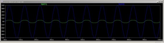
so this was the experiment. the output stage is limited here to about 500mA. the experiment didn't include feedback (or any of the rest of the amp for that matter). the effect is very sensitive to load impedance, so such an output stage would also act much like a tube amp in this respect as well.
Attachments
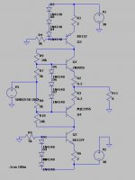
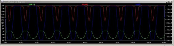
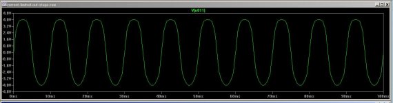
Unclejed, A simulation is a long way from an actual amp, but go ahead and build something and see how it sounds. I think you'll find that a speaker will act quite differently than a resistive load, and that the soft clipping you are seeing in the simulation is really a base current limitation. In the experiments I've been doing on tube amps, the output voltage limit is reached before the current becomes limited.
A 50W amp will clip at about 28V peak to peak into a 2 ohm resistive load. Look closely at the oscilloscope pic I posted in post #4. That 50W amp is delivering nearly 40V peak to peak to the speaker load. I'm trying to think up an experiment that will prove that the 40V peak to peak is louder even though the power increase is not very great.
Below is a dual trace photo of current and voltage in a speaker connected to a 50W at 4 ohm guitar amp. The channels of the oscilloscope were chopped so they occur at the same time. The top trace is current, sensed by a 0.1 ohm resistor, at 5 amps per division. The bottom trace is the voltage across the speaker at 20V per division. Speaker is a Marshall cabinet wired for 4 ohms. Note how the current waveform is more rounded, the voltage waveform is significantly squared off.
Attachments
actually it is louder because it is more power. a 40Vp-p sine wave is 50W into 4 ohms, but a square wave would be approaching 100W. the current peaks are rounded because of the inductive load.
There seems to be a current trend to design solid-state amplifiers with high enough rail voltages to allow similar "inductive peaking".
For example, headroom limit of the amp when it's delivering it's rated clean output power could be about 30Vpeak, and at this point the amplifier would also begin to clip. The amplifier's rails on the other hand could be made as high as +-45V so that inductive peaking (that occurs when a high-output impedance amp drives an inductive load with a clipped signal) can have the (theoretically) 15 volts of extra headroom. Upping the rail voltage like this really doesn't add excessive additional costs since you can design for the intented output power level practically ignoring the extras; you only need that extra 15V swing for momentary peaks and therefore there are little worries about rail voltage sagging due to sustained loading or about the amplifier having to dissipate more waste power during sustained clipping conditions. It's just "dirty" headroom, like in some tube amps. No magic to it. I have seen several examples of solid-state amps that both transition to power amp overdrive softly as well as start to introduce similar inductive peaking as some tube amps when they are hooked to an inductive load instead of resistive one.
With that said, I have also seen a great share of tube amps that hard clip, even to an inductive load, and show absolutely no "peaking" whatsover when the clipping occurs. It all depends on design.
OP's ideas are not too far off from Robert Gallien's introduced in the early 1970's. Their "current limiting" amps had either
- Variable constant current source for the input phase inverter stage. (which was furtherly coupled to push-pull transistor stage hooked to an output transformer, just like typical tube amps). This provided variable soft clipping and output power level control... yep, maybe about 10 years ahead similar schemes appeared to tube amps. In these amps the soft clipping orginated in the PI stage.
- Variable VI limiter for the output transistors. These were in their bigger bass and guitar amps that didn't have the output transformers. In these amps the clipping originated in the output transistors.
Yep, nothing new under the sun. Even soft clipping solid-state amps are some 40-year old technology.
Last edited:
Teemu, thanks for posting on this subject. Unclejed, if you are interested in further study on this subject, you should read Teemu's book. I highly recommend it. Here is a link to where Teemu posted a link to his book over on the Solid State Guitar forum: Book about solid-state guitar amplifiers
You may have to join to view the post. Also there is a member over there that has done quite a lot of work on this subject. His name is KMG.
You may have to join to view the post. Also there is a member over there that has done quite a lot of work on this subject. His name is KMG.
tnx, i was able to download it just fine. great book Teemuk.
the idea of using a sagging supply for extra headroom has been around since the 70's. the power transformer (in addition to rather large filter caps)is the key in some home audio amps from the late 70's.
NAD amps in the early 80's had a soft clip circuit. the soft clipping was done on the input, and kept the amplifier out of saturation, as well as producing a more tolerable sound than hard clipping.
A Gibson SG was played through the amp at fairly high volume. Compare to AC/DC's "You Shook Me All Night Long". The scope is a Tektronix 7104 with fairly long display persistance. At times (not shown) you can see inductive spikes create voltages at the speaker that are well off screen horizontally. These are where the plate voltage goes negative on one output tube while the other tube sees several thousand volts.
Until the moment I've read this underlined sentence, I've been in the strong believe that clamping diodes from each plate terminal of the OPT's primaries to ground were a reliable technique to prevent both tubes and OPT from damage, in case of accidentally operating a guitar amplifier without load. Do I have to drop away my faith?
Best regards!
You normally don't see the spikes until the amp is overdriven pretty hard, so much so that grid current in the output tubes accumulates on the coupling capacitors and re-biases the stage so that there is a dead zone (neither tube is conducting) in the crossover region. Those spikes can breakdown the insulation in the output transformer or the tube sockets. The diodes will stop the spikes although leakage inductance will allow a reduced spike on the side of the OT that goes positive. A resistor of prehaps 200 ohms 10W across the speaker terminals and/or a so called conjunctive RC network across the OT primary can also be used, alone or in combination. Keep the faith! An OT saved is an OT that will still make music.
tnx, that explains the purpose of the large 180 ohm resistor on the speaker plug board on Line 6 tube amps... some Fender amps have a shorting switch in their speaker plugs.
Great thread !My Fisher amp rated max power 40 was per ch has a pre clipping pwr of 28wt/ch. Is that ok? Could old but functional electrolytic filter caps have any relation? Thanks Martin
- Status
- Not open for further replies.
- Home
- Live Sound
- Instruments and Amps
- soft clipping from current limited power supply