H
HAYK
I need to limit the output current depending on the Vce of output transistors as is done in several chip amps. Is there a working example or once again I must reinvent the wheel?
There is the "old school way" - output stage VI limiter (below1)
Or , opto based and/or software based threshold trigger. Full VI protection circuit...
Either way , you could tweak the response to any OPS SOA (voltage dependent).
Both techniques monitor emitter resistor current.
OS
Or , opto based and/or software based threshold trigger. Full VI protection circuit...
Either way , you could tweak the response to any OPS SOA (voltage dependent).
Both techniques monitor emitter resistor current.
OS
Attachments
You need to recalculate the wheel for your particular application.
The ones here will work on most amps, but the values here are specifically for +/-27-ish volts, running down to 2 ohms with 3 parallel pairs. Any other configuration and it needs to be recalculated.
The ones here will work on most amps, but the values here are specifically for +/-27-ish volts, running down to 2 ohms with 3 parallel pairs. Any other configuration and it needs to be recalculated.
Attachments

Yes , how many pairs .. X times SOA , and whether you are triggering a BJT (.6V) or a infrared LED (1.2V-opto).
OS
OS
Yes , you must. VI limiter on the chip amp was calculated to that IC's output devices.I need to limit the output current depending on the Vce of output transistors as is done in several chip amps. Is there a working example or once again I must reinvent the wheel?
They must have rail dependent scaling of the VI integrated , as well.
OS
H
HAYK
The outputs are MJL21193-4. The current should be limited to 17A up 0V to 17V to decrease gradually to 2A at 90V.
I am designing for the Blamless CFP, it has 2x 0.1 ohm emitter resistors. I can't use the circuit on post 2 as it is but I will see how to add a zener diode. Thanks OS.
@wg_ski, thank you for posting.
I am designing for the Blamless CFP, it has 2x 0.1 ohm emitter resistors. I can't use the circuit on post 2 as it is but I will see how to add a zener diode. Thanks OS.
@wg_ski, thank you for posting.
Those are "beefy". Short of a VI DAC ...scaling is in the realm of a specialized IC. I build my protection (s) knowing my rail voltage andThe outputs are MJL21193-4. The current should be limited to 17A up 0V to 17V to decrease gradually to 2A at 90V.
I am designing for the Blamless CFP, it has 2x 0.1 ohm emitter resistors. I can't use the circuit on post 2 as it is but I will see how to add a zener diode. Thanks OS.
output stage configuration.
BTW , why you bother with CFP's , EF2/3 can sound better , go faster ... and be more stable. You do lose 2-3V .. however.
PS - CFP is not faster than a CFA Wolverine EF3 - 325V/us ... nothing beats it. I have no idea why the old P3A has any "attraction"
when there are so much better designs here on DIYA. Unless you want distortion and instability ???
OS
Last edited:
H
HAYK
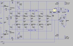
I developed the idea of post 2 to this circuit.
The R6,R4, adjust first for maximum current with supply 15 , the R2+R7, adjust the current at 0V out. The ratio if found to get 8V at R7 and R5 is adjusted for minimum current for 2x supply.
This circuit doesn't limit, it shuts down when current exceed, need to off_on to reset. This how it doesn't distort.
I will try out on the Blamless CFP if you want to follow the evolution.
Attachments
VI protection is not popular because it has serious stability problem that backfire with shoot-through from oscillation. Efforts to stabilize it usually slow it down so make it less effective. I think a better protection would attenuate the input/gain rather than instantaneous output limiting. Anything that changes the output impedance is probably going to be a bad idea. I suppose that includes current limiting. VI limiting driving a transformer is a recipe for disaster. Consider what you need to do to protect the output from an external voltage.
H
HAYK
I did see the current limiter is linear and in negative feedback. That is before limiting current reaches, it may oscillate and also distort. I remembered Pionneer uses SCR mounted transistors to shut down when current surpassed. As I have only 0.6V to short, SCR which needs 1.2V minimum cannot work. I can short the input signal by an opto coupler but it is again in negative feedback, again I must use shut down.
I want to mention that the proposed by OS in post 2 puts the output in limitation by output voltage which is OK with resistive load but dramatic with reactive kind. The one proposed by @wg_ski keeps the current limiter at 0V value when it goes to opposite phase. This also can have problem with reactive loads.
Maybe I am overdoing it, @wg_ski's proposition maybe sufficient to protect from output shorted and allow high currents with low Vce.
I will study it in depth to get it shut down instead of limiting.
That particular one limits to 3 amps per transistor into the zero crossing, and stays at 3A when the current flows “the wrong way” due to reactance. In practice, that current only exists for a quarter of a cycle or less at a time and even 3055’s will survive that on sub-30 rails. To make the current drop further in the third quadrant one resistor from the base of the protection transistor to the supply is needed. Then recalculate everything. For amps on very high voltage supplies it’s usually a good idea. For the typical 50-ish volt rails or lower and high SOA transistors (Toshiba, Sanken, ON) it’s usually unnecessary. The big boys will take 3A and 100V for 10 ms or less at a time.
I find shutdown on SOA protect quite annoying. For a pro audio situation it’s not an option. They do sound bad when they activate, but it’s better than cycling power to get sound back. To make the action less obtrusive, activate the clip limiter. The protect circuit causes loss of feedback, same as clipping. If a clip limiter is engaged it will dial back the volume gracefully after SOA limiting for a couple cycles. Some of the bigger pro amps directly activate the clip limiter with the SOA protect transistors rather than clamping the VAS.
I find shutdown on SOA protect quite annoying. For a pro audio situation it’s not an option. They do sound bad when they activate, but it’s better than cycling power to get sound back. To make the action less obtrusive, activate the clip limiter. The protect circuit causes loss of feedback, same as clipping. If a clip limiter is engaged it will dial back the volume gracefully after SOA limiting for a couple cycles. Some of the bigger pro amps directly activate the clip limiter with the SOA protect transistors rather than clamping the VAS.

The traditional discrete circuit need large value capacitors to allow the fast peaks permitted in the SOAR graphs. These cannot be integrated, so I presume that ICs use a more direct transistor temperature monitoring. This can be far faster than measuring a discrete can temperature and therefore, more effective
I don't use "the old school way" like the crude example I posted.
I use the OPTO (below) . It looks for overcurrent "violations" by both occurrence and duration.
Software determines what durations and/or occurrences trigger a shutdown.
Highly effective. One could program where occasional "violations" would NOT create a trigger.
OS
I use the OPTO (below) . It looks for overcurrent "violations" by both occurrence and duration.
Software determines what durations and/or occurrences trigger a shutdown.
Highly effective. One could program where occasional "violations" would NOT create a trigger.
OS
Attachments
H
HAYK
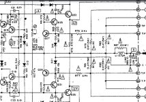
This is Pioneer shut down SCR with wg_ski type SOA.
For domestic use a short happens rarely, if so, to off_on is not a problem unlike in professional use.
In my case, the VAS is not current limited and can pump 730ma in the limiter. I will rather shut down the VAS and the CCS simultaneously with either pole overcurrent detect.
For domestic use a short happens rarely, if so, to off_on is not a problem unlike in professional use.
In my case, the VAS is not current limited and can pump 730ma in the limiter. I will rather shut down the VAS and the CCS simultaneously with either pole overcurrent detect.
Attachments
H
HAYK
As I have only 0.6V, I created a 1.2V by bootstrap. This keeps the amp off when both poles have switched protection. Bellow is only the positive, the negative is symmetrical.

CFP are easier to thermally stabilize as the output devices + heatsink are not in the thermal loop, and adding base resistors to stop VHF oscillation is a simple fix for that mode of instability. The much lower bias current and larger voltage swing both increase power efficiency - so there's a lot going for CFP topology (not including the ability to add a little gain so the VAS doesn't clip first).EF2/3 can sound better , go faster ... and be more stable. You do lose 2-3V .. however.
- Home
- Amplifiers
- Solid State
- SOA current limiter, any example?