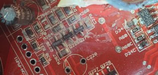
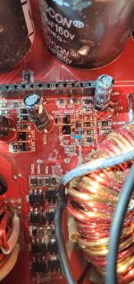
I am trying to identify Q81 in a Skar RP-4500. I believe its part of the remote or protection circuit. I dont know what to replace it with.
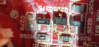
I believe the identifier is W6 and the P is the date code. I dont know which manufacture uses this style of date code marking. It appears to be the same transistor used in Q275. See attached.
I believe it is a pnp because I have tested in diode check off board.
black probe on base red probe on collecor =.701v
black probe on base red probe on emitter = .012v
in resistance mode its showing 25 ohms between the base and emitter.
Attachments

Last edited:
I pulled Q275 off the board and there is no connection to the emitter pin of a standard sot-23 so my guess is it is a zenner. I will just check the one without the short with a 1k resistor and 9v battery to confirm and report back.
Was there an independent trace going to the open leg?
Some amps have started using a JFET in locations marked Q81 and Q275.
Is it possible that Q81 is OK and Q275 is defective?
Some amps have started using a JFET in locations marked Q81 and Q275.
Is it possible that Q81 is OK and Q275 is defective?
It is possible seeing as i have no signs of life and the relay doesn't engage and i believe Q275 is part of the remote circuit but i am unsure.
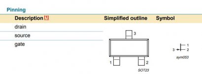
Q275 pin 1 is directly connected to ground.
Pin 3 of Q275 is connected to the base of Q225 (2sc2412k).
Pin 3 of Q275 to ground i measure 99.7kΩ
Q275 pin 1 is directly connected to ground.
Pin 3 of Q275 is connected to the base of Q225 (2sc2412k).
Pin 3 of Q275 to ground i measure 99.7kΩ
Attachments
Last edited:
Starting with resistance mode.
Red on pin 1.
Black on pin 2: OL
Red on 1 Black on pin 3: starts at 45Ω and decreases to 25Ω with a time span of about 20 seconds.
Black on 1 Red on 2: 6.6MΩ
Black on 1 red on 3: starts at 45Ω and decreases to 25Ω with a time span of about 20 seconds.
Diode Mode:
Red on 1 Black on 2: OL
Red on 1 Black on 3: Starts at .040v and drops down to .015
Black on 1 red on 2: .703v
Black on 1 red on 3: .015V
The prefix codes are often location of production.
The diagrams that use this diagram (I can't post them) simply has 111 as the part description.
no need to repost.
The diagrams that use this diagram (I can't post them) simply has 111 as the part description.
no need to repost.
Drain to source resistance of the MMBFJ111 is 30 ohms and I was at about 25 ohms. This would explain a lot. Q275 is open drain to source and Q81 checks out fine.
Boy was this a learning experience for me. I have to read more on Jfets now.
Boy was this a learning experience for me. I have to read more on Jfets now.
- Home
- General Interest
- Car Audio
- SMT Identification "W6" or "W6P"