Hi!
I do have one small SMPS from USHIO, made for powering xenon lamp....but in original it did have uPC1042 PWM, which is absolete and I can't get it, so i did put in a SG3525 and just connected it to driving transformer, altrought before was some PNP between uPC and transformer.
So, Vc (pin13) of SG is connected to Vcc su on outputs I have max voltage, driving transformer has two primary windings and middle is connected to Vcc, before one was connected to transistor which was driven by uPC, and other true diode do gnd. I did try that way but than signal wasn't square, just some blah....
Anyhow, I did connected output of SG true 1uF cap to trafo directly, signa, is square and just okay, but problem is when I turning pot to increse duty cycle power goes up (voltage and current on load) but on about 20-25% of duty it stop to raise, even duty on SG is raising, but output stops to raise, even current fall of a bit.
I did try to put pair of transistors between uPC and transformer like it was in original, but no, also I did try to put two BD139/140 to work as push pull but still same, bad signal.
SG and is powered from 15V stab, I did try to power it at higher voltage (26V) and than I have bigger max power for about 10-20%, but still, after I increase duty above 30% or so on output transformer is just stop to raise.
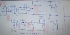
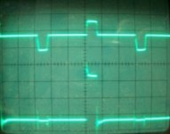
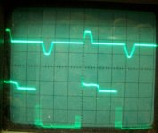
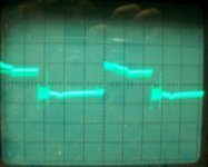
There are schematic, two oscilograms, upper is output of main hf transformer and down is output of sg.
thanks for help and advices!!
I do have one small SMPS from USHIO, made for powering xenon lamp....but in original it did have uPC1042 PWM, which is absolete and I can't get it, so i did put in a SG3525 and just connected it to driving transformer, altrought before was some PNP between uPC and transformer.
So, Vc (pin13) of SG is connected to Vcc su on outputs I have max voltage, driving transformer has two primary windings and middle is connected to Vcc, before one was connected to transistor which was driven by uPC, and other true diode do gnd. I did try that way but than signal wasn't square, just some blah....
Anyhow, I did connected output of SG true 1uF cap to trafo directly, signa, is square and just okay, but problem is when I turning pot to increse duty cycle power goes up (voltage and current on load) but on about 20-25% of duty it stop to raise, even duty on SG is raising, but output stops to raise, even current fall of a bit.
I did try to put pair of transistors between uPC and transformer like it was in original, but no, also I did try to put two BD139/140 to work as push pull but still same, bad signal.
SG and is powered from 15V stab, I did try to power it at higher voltage (26V) and than I have bigger max power for about 10-20%, but still, after I increase duty above 30% or so on output transformer is just stop to raise.
There are schematic, two oscilograms, upper is output of main hf transformer and down is output of sg.
thanks for help and advices!!
Attachments
This can not work without output inductor! You have square wave after transformer and there is no rectifier that can work with capacitive load only.
You will find that TL494 is much more similar to UPC1042 than SG3525A.
Bipolar transistor switching stages with a pulse transformer are usually not driven like MOSFET stages. Try to understand the original circuit, it should be similar to the one used on AT PC power supplies, it's called "proportional drive". The bridge turns on by itself when the control IC stops shorting the pulse transformer secondaries in one direction, and it turns back off when it starts shorting it again.
You are very lucky if you have not blown the SMPS already due to improper drive.
You are very lucky if you have not blown the SMPS already due to improper drive.
Well.....I'm the man 🙂
I was think to use mosfets like IRFP450 here, I did mod the drive transformer so I did add some windings and now I have 10V on output which is just enought for this IRFP's....also voltage drop is smaller on them, than on bipolar.
- Status
- Not open for further replies.
- Home
- Amplifiers
- Power Supplies
- SMPS won't get max voltage/current