Hi,
for startup sequence, yes, is possible unbalanced but think it's catastrophic for audio (the frequency varies continuously with the load). apart from the imbalance
in the case of dual output.
for startup sequence, yes, is possible unbalanced but think it's catastrophic for audio (the frequency varies continuously with the load). apart from the imbalance
in the case of dual output.
AP2
Did you get my PM?
Please responde
Hi,
I got it but I'm waiting to return to the office after the party.
I think I can answer you Tuesday.
Regards
OK!!!
Happy Easter for All 😉
Hi,
I got it but I'm waiting to return to the office after the party.
I think I can answer you Tuesday.
Regards
Happy Easter for All 😉
HiHi,
certainly is not easy to develop effective protection for the 21531.
But since they wanted to use the 2151.
TL494 is good, Also you can add a driver eg. IR21xx or a transformer to drive the mosfet.
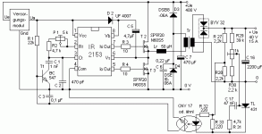
however I've solved the problem at the start of 21531. in the presence of a short circuit or high absorption. I enclose a pic just for curiosity. worked from 2002 until 2007 without problem in class H amps.
I think it works better, less RFI / EMI of some unregulated on the market.
somewhere in this forum I already put the diagram.
Where is a diagram not to wander?
thanks and cheers !
Hi
Where is a diagram not to wander?
thanks and cheers !
Hi,
I not have time for put new, maybe at weekend.
I do not remember where thread I put it, sorry.
If you are interested, I have some pcb (equal to the photo), I think 5-6 pz.
components can be found easily (few components).
I have the PCB and transformer to + /-68v 14Amp, and mosfets.
PCB, MOSFET and small heatsink for 5 pz, I can give.
Regards
Roberto
There dosn't seem to be any creepage and clearance between the high voltage input and the low voltage stuff!
There dosn't seem to be any creepage and clearance between the high voltage input and the low voltage stuff!
??..you mean ac-dc iso? (yes, have 1cm with in side 5mm air gap) this is a ISO line of separation ac-high voltage to dc output.
or you mean dc output to dc low voltage? also this have clearance.
Last edited:
I was looking at the PCB picture on page 1, I couldn't see no obvious space between the high voltage area and the rest.
I was looking at the PCB picture on page 1, I couldn't see no obvious space between the high voltage area and the rest.
My photo is at page 2 "IR21531D", blue pcb.
Help!
Hi Roberto (AP2) !
Please if you are able to set a schematic, PCB-layout and parts list of your SMPS, or sent me on my E-mail.
I need this SMPS (2x35V/2x5A) for the stereo amplifier with TDA7294/4om!
Advance thanks for the great help!
Hi Roberto (AP2) !
Please if you are able to set a schematic, PCB-layout and parts list of your SMPS, or sent me on my E-mail.
I need this SMPS (2x35V/2x5A) for the stereo amplifier with TDA7294/4om!
Advance thanks for the great help!
Last edited:
The layout on page 1 post 1, I would say does not conform to required creepage and clearance distance, wich with the voltages present and working to worse cass class 111 polution should be 4mm clearance and 8mm creepage, or 4mm with a 1mm or wider slot in the PCB to ensure an 8mm creepage distance.
Sorry AP2 I wasn
Sorry AP2 I wasn
Hi Roberto (AP2) !
Please if you are able to set a schematic, PCB-layout and parts list of your SMPS, or sent me on my E-mail.
I need this SMPS (2x35V/2x5A) for the stereo amplifier with TDA7294/4om!
Advance thanks for the great help!
Hi,
ok, I put project in this thread at weekend. maybe can help others diy.
for sub is very good (600-700w)
Regards
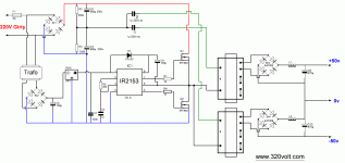
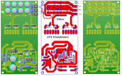
Ok this is main schematic and new layout of PCB. Do anyone have idea for shorst cutcuit protection without curent transformer or curent sens on primary side. Even maybe is better schematic or sugestion with other ic (TL494 on exapmle) but with ATX transforemers in serial for +-50V.
I dont know indutance of that transformer or ratio but on primary side it has 30 turns and on secondary it has 2x7 turns with central GND for 2x12V but in serial its almost 25V. Core is EI 33 without gap
Can one TL494 and one pair of mosfet "push" two of these?
I dont know indutance of that transformer or ratio but on primary side it has 30 turns and on secondary it has 2x7 turns with central GND for 2x12V but in serial its almost 25V. Core is EI 33 without gap
Can one TL494 and one pair of mosfet "push" two of these?
Attachments
Ok this is main schematic and new layout of PCB. Do anyone have idea for shorst cutcuit protection without curent transformer or curent sens on primary side. Even maybe is better schematic or sugestion with other ic (TL494 on exapmle) but with ATX transforemers in serial for +-50V.
I dont know indutance of that transformer or ratio but on primary side it has 30 turns and on secondary it has 2x7 turns with central GND for 2x12V but in serial its almost 25V. Core is EI 33 without gap
Can one TL494 and one pair of mosfet "push" two of these?
Hi,
now pcb is better but not perfect, some layers need modify.
your trafo (pr=30:sec=7) with ir2153 circuit, produces 36,9V per side @ 230 Vac. also, requires low frequency of switch, around 40Khz max.
regards
- Status
- Not open for further replies.
- Home
- Amplifiers
- Power Supplies
- SMPS IR2153 vs ATX transformers


