hi guys
i'm confused about smps inductor!
let explain my problem by some questions:
1-we have a 12v dc battery ,an 1 ohm load, a 47uh inductor(any powder core material)with zero copper loss!, then we connect load and inductor in series with battery,now in this condition do we have any core loss at 12Amps current?(we assume copper loss is zero)
2-do we have DC magnetizing force in that example?and any losses caused by that?
3- now we have a buck converter.output current is 10Amps and current ripple is 0.5Amps at 200Khz Freq.with same inductor what cause losses in core?10 Amps dc output or 0.5 amps ac ripple current?we can calculate B by this formula B=N*I/RA which i is output dc current.but does B causes any loss in core?an is that DC magnetizing force?and when and why we use that?
4-is buck inductor in dc bias condition?
5-in most of powder core datasheet there is a curve named"peak ac flux density VS core loss".can we use that to calculate buck insuctor core losses?
i need your help to understand inductor designing!
As indicated by question 5) core losses are only incurred for AC excitation of the B/H field so DC currents in the winding do not result in losses in the core. They are hysteresis losses. If you look at the B/H plot for any particular core then walking one way up you get one curve and walking the other way down you get another curve. The area inside the curves is the energy lost, hysteresis loss. [E=0.5BXH, it's a cross product, blah]. Sometimes you will get a pair of plots. To be confusing one will be for a DC excitation and one for an AC excitation. The AC one will be distorted and enclose a different area indicative of the fact that loss is a function of frequency.
Your plot of Peak AC Flux Density VS Core Loss is exactly there for the purpose you suggest. To get an idea about core losses for your particular design. It is however more appropriate for transformer design because for an inductor both AC copper and core Losses are much lower. Something like...
http://www.ti.com/lit/an/slva477b/slva477b.pdf
You design for 20-40% ripple current, ripple flux. Based on Bsat, for the DC current, your AC core excitation will be 20-40% lower and the associated losses much lower, it's not a linear relationship.
The loss curves are, as it says, plotted for Peak Flux excursion. In a transformer/Inductor design you generally end up with a figure that is the Peak to Peak excursion and therefore you take half that value before using the plots. It is generally quoted as Pv in units of kW per m^3 so having found a number for Pv you work out the core loss by multiplying that number by the effective volume, Ve, of the core, or pair of core halves, taking into account that Ve is given in mm^3, a factor of 1E9.
If you are in America there may be some other unit conventions involved so you have to adjust for foot-pound-slug-ergs, divide by PI^3/2 and multiply by 10,000.
Last edited:
As indicated by question 5) core losses are only incurred for AC excitation of the B/H field so DC currents in the winding do not result in losses in the core. They are hysteresis losses. If you look at the B/H plot for any particular core then walking one way up you get one curve and walking the other way down you get another curve. The area inside the curves is the energy lost, hysteresis loss. [E=0.5BXH, it's a cross product, blah]. Sometimes you will get a pair of plots. To be confusing one will be for a DC excitation and one for an AC excitation. The AC one will be distorted and enclose a different area indicative of the fact that loss is a function of frequency.
Your plot of Peak AC Flux Density VS Core Loss is exactly there for the purpose you suggest. To get an idea about core losses for your particular design. It is however more appropriate for transformer design because for an inductor both AC copper and core Losses are much lower. Something like...
http://www.ti.com/lit/an/slva477b/slva477b.pdf
You design for 20-40% ripple current, ripple flux. Based on Bsat, for the DC current, your AC core excitation will be 20-40% lower and the associated losses much lower, it's not a linear relationship.
The loss curves are, as it says, plotted for Peak Flux excursion. In a transformer/Inductor design you generally end up with a figure that is the Peak to Peak excursion and therefore you take half that value before using the plots. It is generally quoted as Pv in units of kW per m^3 so having found a number for Pv you work out the core loss by multiplying that number by the effective volume, Ve, of the core, or pair of core halves, taking into account that Ve is given in mm^3, a factor of 1E9.
If you are in America there may be some other unit conventions involved so you have to adjust for foot-pound-slug-ergs, divide by PI^3/2 and multiply by 10,000.
lets use numbers.i have a buck converter working at 180KHz.input voltage is 13volts and output voltage is 7volts at 10amps.my goal is 5% ripple in ouutput current means 0.5amps.so i need a 36uh inductor at 10amps.
that app note helped but my qestion exacly is about core losses calculation.
output current has two terms: DC and AC(ripple) right?
do that 10amps dc current produce any losses in inductor core?or just that 500ma ripple current causese losses in core?and therefore if we use greater inductance means lower ripple current and then core losses become very low!!am i thinking right?
we can calculate B by this formula B=NI/RA , is this formula and calculated B useful for cor losses calculations?
in a transformer like fullbridge trnsformer we can easily use V=4.44NFBA to calculate B and then by using "peak ac flux density vs core loss"curve calculate core losses.but in an inductor we can't use that formula and i think this formula B=NI/RA isn't useful too for core loss calculation.
so how we can calculate losses??!!i havn't any idea
Last edited:
Magnetic core losses (as opposed to eddy current losses) depend on the DC current, not just the AC ripple current, because the hysteresis curve varies for different DC offsets. Its quite complex, but note that the inductance itself will vary (fall) with increasing DC current as saturation is approached. These losses scale with frequency as each magnetic reversal loses energy.
Eddy current losses depend on the amplitude of magnetic field variation, the core conductivity and the skin-depth of the core material at the frequency in question.
Basically inductors are complicated (and I haven't even mentioned skin effect or proximity effect in the windings).
Eddy current losses depend on the amplitude of magnetic field variation, the core conductivity and the skin-depth of the core material at the frequency in question.
Basically inductors are complicated (and I haven't even mentioned skin effect or proximity effect in the windings).
Mark mentions that DC bias does affect losses and goes on to mention other loss factors which are taken into account when the core loss with frequency and flux excursion are taken into account. So much of it is already covered apart from the DC bias... but for practical purposes you get to ignore that. If you are operating a core, with small ripple, so close to saturation then your design will likely have other problems.
It's magnetics design. Get close to a wrong answer first and then iterate through your design choices.
You're thinking, trying or looking to minimise inductor ripple current, is kind of the wrong way around. In bulk terms Inductors are rubbish at storing energy when compared to capacitors. Designing a large inductor with small ripple is asking for high energy storage. Large inductors, any inductor but in particular large ones, also don't like having the current through them changed too quickly. It really really hurts the speed of your regulation loop if you implement feedback and hurts the output response without feedback.
The 20-40% ripple current is one of those general close to ideal compromises between losses and transient performance, and cost. You don't design output filters in an SMPS based on the concepts of small signal filters you target output ripple voltage and loop performance. Don't get too precious and worry over much about details. Find a result first then check and iterate to the solution.
Your goal is not 5% ripple current. The inductor will be too big and the loop horribly slow as a result. It will spend most of it's time against the stops as it tries to slew the inductor current in response to transient demands. 20% ripple will be four times as fast. 40% ripple eight times as fast. Fast is good.
You goal is output ripple voltage and output voltage deviation in response to transient load demands. That is determined in the first instance by output filter capacitance ESR and in the second by... output filter capacitance ESR. Don't chase esoteric low/zero ESR small value film capacitors. The loop becomes a pain.
Just pick your easiest to source range of radial low ESR 105C aluminium electrolytics with meaningful Data Sheets. What used to be Philips, then BHC and now Vishay 136 RVI. Random...
Low ESR | Aluminum Electrolytic | Capacitors | Vishay
https://www.vishay.com/docs/28321/136rvi.pdf
Your output current is 10A. Your ripple current, 20%, is 2A. You want, can accept, 50mV output ripple voltage. You want an ESR of 50mV/2A or 25mR. Your input voltage is 13V. Assume that if things go wrong your capacitor is going to see that voltage. Pick a voltage rating above this, 16V or to be really safe 25V. Find a capacitor that matches the required ESR and has a 2A ripple current rating. 25V 2200u 16X31. Use two for the extra feel good factor. Make sure you lay out the board so they see the same. Anything tight and thick enough. Check the graphs on the data sheet for frequency/temperature dependencies. This is why you chose a range of capacitors that came with a good, comprehensive, data sheet.
Don't use formulae that include the number 4.44 Those are for sinusoidal excitation voltages. If someone gives you a formula with 4.44 in it. Ignore them. You are dealing with square wave voltages.
Assume Bsat is 300mT. With 20% ripple current your peak to peak flux excursion is 20% of this or 60mT. Half that for the peak and the number you plug in the Pv graph is 30mT. For any, ferrite, material worth its salt you will get a Pv value down in the hundreds, tens or less kW/m^3. The core loss can effectively be ignored. With convection cooling in a transformer design you might start to worry if you are reaching 1 thousand kW/m^3. Notice how no formula was involved.
Your target ripple current is 2A. During switch off time the inductor gets reset through the output voltage plus a diode drop or 7.6V. Your duty cycle is about 50% so the off time is about 3.33uS. Yes you could be more accurate with the sums but ¯\_(ツ)_/¯
dI/dT = Voff/L
L = Voff.Toff/dI
L = 7.6x3.33E-6/2
L = 12.7uH
Fudge equation. These never work. Sometimes they do but many times the estimate turns out to be silly and you have to make other choices.
AwAe = LIpkIrms/BsatJKcu
AwAe is an area product. Winding Area/Core Area. L is your inductor value. Ipk is the average output current plus half ripple, 10A + 1A = 11. Irms is the rms inductor current. Your average or 10A. Bsat = 300mT. J is the wire current density. 4E6 A/m^2. Kcu is copper utilisation. 0.7 for round wire.
AwAe = 13uH x 11 x 10/0.3 x 4E6 x 0.7
AwAe = 1.702E-9
Assume Aw = Ae = SQRT 1.702E-9 = 42 mm^2
https://www.tdk-electronics.tdk.com...2ba503/ferrites-and-accessories-db-130501.pdf
EFD25 = 58mm^2 Page 546/547
Minimum turns to avoid saturation.
Nmin = LIpk/Bsat.Ae
Use short circuit current for Ipk... 15A
11 turns. The required Al value is 13E-6/11^2 or 107nH. You will have to use the formulae elsewhere to find an unequal gapped pair to achieve this. "Calculation factors (for formulas, see “E cores: general information”, page 402/403)"
Then you have to fit 11 turns on the bobbin in a way that makes sense and takes AC copper losses, skin/layer, into account. Same as you did for your transformer but, as was the case with core losses, the copper losses will be markedly reduced. 11 turns 6 by 0.5mm rope as a single layer?
Last edited:
thank you MorbidFractal you are awesome.
i check inductor design app from magnetics and my toughts was right.
lower inductance means higher ripple and this ripple produce losses in core.by increasing inductance core loss become very low near zero!(but increase in copper loss)and DC current has not affetc on core loss.it just affect on DC magnetizing forece and reducing permability an change on real inductance.
you say by increasing ripple current (going near D.C.M mode)loop response become faster.but as resault core losses become very high,peak current become high,skin effect and proximity effect become high and other disadvantage.my load is sensitive about ripples and need more smooth current.so i need 5% ripple current.
now i use a Koolu powder core from magnetics inc (toroid) and core losses is almost zero,copper losses is 1 watt at 10 A and every thing is ok.core diameter is 27mm and my inductor is small.
My head is stuck in ETD and EFD ferrite cores. You seem to have arrived at the right ideas. My assumption of an output voltage requirement was misplaced.
If you want to go mad or otherwise be evil then...
http://www.audiodesignguide.com/ClassD/azrtatad.pdf
https://www.ti.com/lit/ml/slup105/slup105.pdf
Coupled inductors again. The method proposed by Dixon gets in the order of 10% leakage inductance.
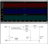
You design the inductor as per the previous for Lmain then Lcoup is wound close to the core. Lmain is wound on top with the spacing between the windings. Lcoup carries the, low, ripple current no DC. Lmain carries the high current DC. Lcoup thin wire for 1A AC. Lmain thick for 10A DC. You more or less don't care about skin/layer effect.
Don't worry too much about Dixon's inductor being 2mH and yours being 11uH. It's the winding geometry that sets the leakage ratio.
CFILT is sort of chosen to such that the resonant impedance SQRT(LLEAK/CFILT) is close to that of your load impedance. Otherwise you have to insert some damping into the circuit. The bigger CFILT is the smaller the output ripple.
You use Current Mode Control with feedback from RSNS referenced to ground to control output current. It is located outside of and therefore not affected by the resonance but does measure the total load current.
It's almost one of those things where you just build it then measure how it behaves and bodge on the right values later.
As shown output ripple current is 63mA peak to peak. 0.3%
...
If you want to go mad or otherwise be evil then...
http://www.audiodesignguide.com/ClassD/azrtatad.pdf
https://www.ti.com/lit/ml/slup105/slup105.pdf
Coupled inductors again. The method proposed by Dixon gets in the order of 10% leakage inductance.
You design the inductor as per the previous for Lmain then Lcoup is wound close to the core. Lmain is wound on top with the spacing between the windings. Lcoup carries the, low, ripple current no DC. Lmain carries the high current DC. Lcoup thin wire for 1A AC. Lmain thick for 10A DC. You more or less don't care about skin/layer effect.
Don't worry too much about Dixon's inductor being 2mH and yours being 11uH. It's the winding geometry that sets the leakage ratio.
CFILT is sort of chosen to such that the resonant impedance SQRT(LLEAK/CFILT) is close to that of your load impedance. Otherwise you have to insert some damping into the circuit. The bigger CFILT is the smaller the output ripple.
You use Current Mode Control with feedback from RSNS referenced to ground to control output current. It is located outside of and therefore not affected by the resonance but does measure the total load current.
It's almost one of those things where you just build it then measure how it behaves and bodge on the right values later.
As shown output ripple current is 63mA peak to peak. 0.3%
...
Attachments
Last edited:
using gapped ferrite as inductor is complicated.because DC bias characteristic VS permability is unknown and calculating real inductance under load is very difficult.so i think using powder cores like MPP or SENDUST or ... is better idea.(my experience)My head is stuck in ETD and EFD ferrite cores. You seem to have arrived at the right ideas. My assumption of an output voltage requirement was misplaced.
If you want to go mad or otherwise be evil then...
http://www.audiodesignguide.com/ClassD/azrtatad.pdf
https://www.ti.com/lit/ml/slup105/slup105.pdf
Coupled inductors again. The method proposed by Dixon gets in the order of 10% leakage inductance.
You design the inductor as per the previous for Lmain then Lcoup is wound close to the core. Lmain is wound on top with the spacing between the windings. Lcoup carries the, low, ripple current no DC. Lmain carries the high current DC. Lcoup thin wire for 1A AC. Lmain thick for 10A DC. You more or less don't care about skin/layer effect.
Don't worry too much about Dixon's inductor being 2mH and yours being 11uH. It's the winding geometry that sets the leakage ratio.
CFILT is sort of chosen to such that the resonant impedance SQRT(LLEAK/CFILT) is close to that of your load impedance. Otherwise you have to insert some damping into the circuit. The bigger CFILT is the smaller the output ripple.
You use Current Mode Control with feedback from RSNS referenced to ground to control output current. It is located outside of and therefore not affected by the resonance but does measure the total load current.
It's almost one of those things where you just build it then measure how it behaves and bodge on the right values later.
As shown output ripple current is 63mA peak to peak. 0.3%
...
coupled inductor design is useful when lowest ripple current is our goal, is that right?so when we don,t need that very low ripple current using simple inductor is enough.
another question: can we using dual phase(interleave) buck converter as alternative way instead coupled inductor technique?
That's not strictly the case. The characteristics of a gapped inductor are largely determined by the gap. The problem is getting the right size gap in standard halves. In powder and similar cores the gap is intrinsic so you have to by from the available range of permeabilities. It's kind of the same difference but you are more likely to find a manufacturer producing a wide range of permeabilities.
Coupled inductor design is a bit niche. That probably should be taken as meaning I don't know enough about it or have otherwise been disappointed in my ability to implement it satisfactorily . Most times I would have to add extra circuit damping wasting more power than I would like. Things get horrible if you find one of the resonances internal to a loop that you wish to regulate.
Interleaving does give ripple current cancellation but only for certain duty cycles dependent on the number of phases so 50% for two phases or 25%, 50%, 75% for four phases. The input/output voltage ratios have to be well defined.
Great discussion, thanks MorbidFractal for an excellent & practical overview!
A few capacitor related questions:
I know you said "Don't chase esoteric low/zero ESR small value film capacitors. The loop becomes a pain" but many switcher chips assume MLCC's
1. MLCC's can have very low ESR to minimise ripple voltage but how to determine ripple current ratings? Without Ir ratings can DF be used to estimate self heating? What is an acceptable level of heating?
3. How painful does loop compensation become? Isn't that just the price to be paid for a fast converter?
2. Is there a rule of thumb for estimating Ir in electros at frequencies higher than the usually quoted 100kHz? Will the effect of heating increase with the square of frequency and hence reduce Ir proportionately?
Cheers, Ralph
That's not strictly the case. The characteristics of a gapped inductor are largely determined by the gap. The problem is getting the right size gap in standard halves. In powder and similar cores the gap is intrinsic so you have to by from the available range of permeabilities. It's kind of the same difference but you are more likely to find a manufacturer producing a wide range of permeabilities.
Coupled inductor design is a bit niche. That probably should be taken as meaning I don't know enough about it or have otherwise been disappointed in my ability to implement it satisfactorily . Most times I would have to add extra circuit damping wasting more power than I would like. Things get horrible if you find one of the resonances internal to a loop that you wish to regulate.
Interleaving does give ripple current cancellation but only for certain duty cycles dependent on the number of phases so 50% for two phases or 25%, 50%, 75% for four phases. The input/output voltage ratios have to be well defined.
take a look at this curves.
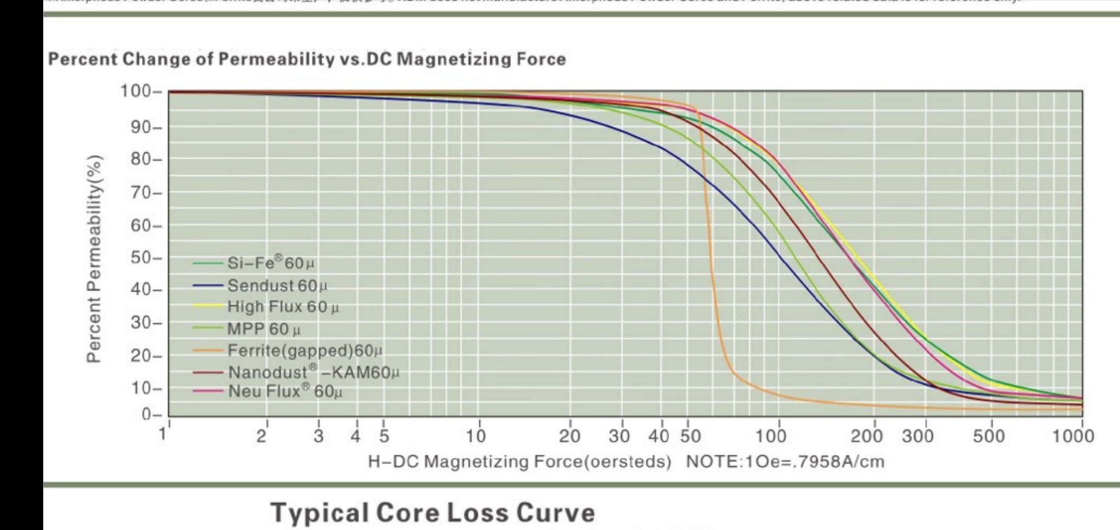
a little change in current causes a huge change in H.but in powder core it's not.
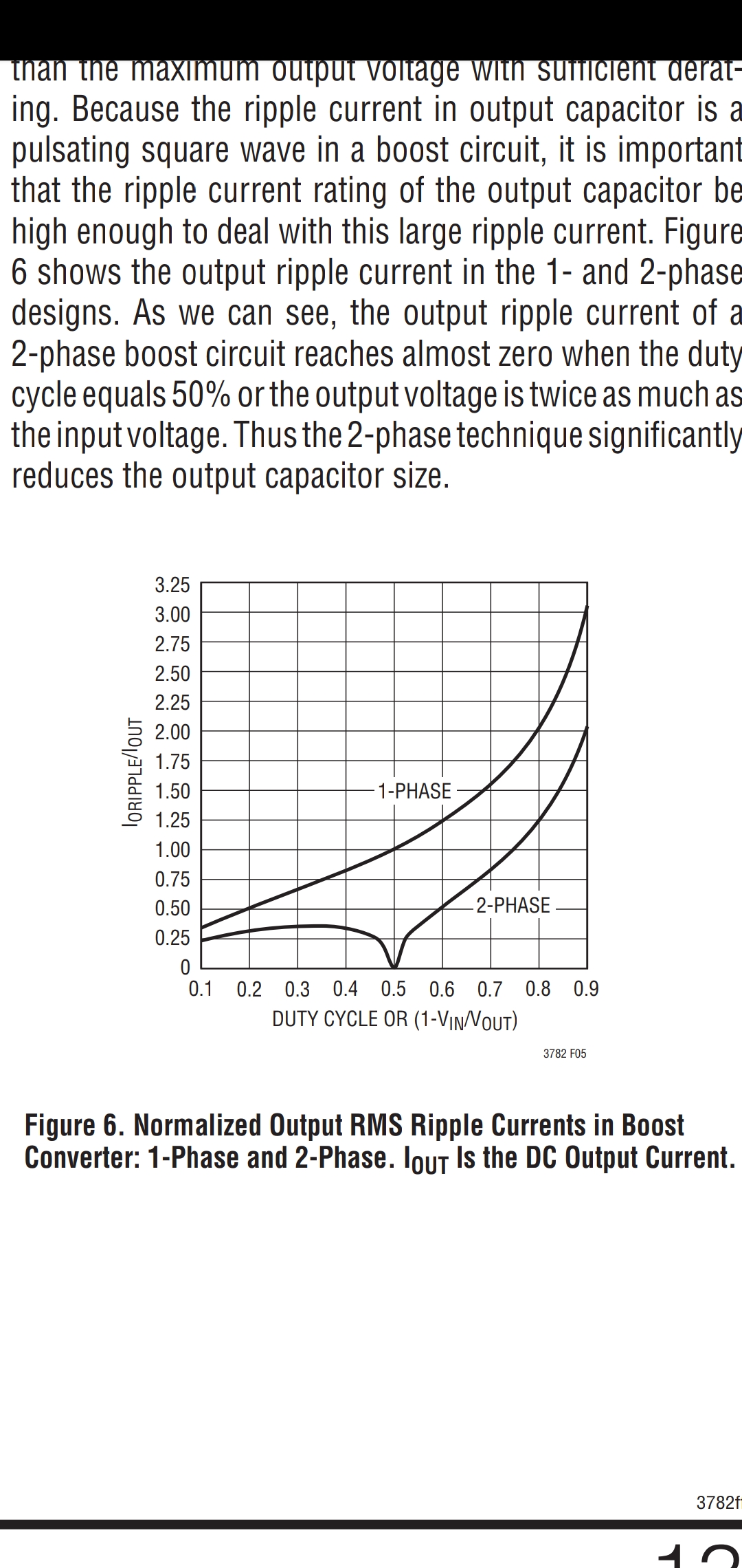
another graph shows 2-phase interleave has less current ripple than 1-phase at any duty cycle specially at 50% duty
Sorry. Point, kind of, taken. Yes for pure ferrite the transition is sharp. You design so you do not hit it. Soft materials are... soft.
In respect of your ripple current graph it is given for a boost convertor. I was referring to your buck convertor.
As your picture suggests in a boost convertor the output current is discontinuous so, although inductor ripple current contributes to output ripple current it is not overly significant.
- Home
- Amplifiers
- Power Supplies
- smps inductor