Has anyone tried to power a RIAA with a smps?
I'm working on a pcb, and wonder if this is a good solution or it has more problems than advantages.
I'm working on a pcb, and wonder if this is a good solution or it has more problems than advantages.
the lowest noise SMPS controllers I have seen have noise circa 100 uV -- on the same order of magnitude of a MC cartridge -- so you have your work cut out for you -- consider using something like the LT3439 or LT1683 (Linear has a couple more ultra LN regs) with their ULN linear regulators operating in "post" fashion -- and a couple of micro-henries of inductance in the power leads.
I think the main reasons to use a SMPS are small size and/or high effeciency. Neither of them is important for a RIAA amp.
I think also noone here manage to do an ultra quiet SMPS. I mean high end here but if you only want to play some records I think it's quite possible to use some modern SMPS.
I think also noone here manage to do an ultra quiet SMPS. I mean high end here but if you only want to play some records I think it's quite possible to use some modern SMPS.
Size could be an issue, but not too much. I was thinking that if the smps has it's noise placed higher than 40Khz (for instance), all this ripple would be inaudible. I know psrr drops very fast, but as I've seen happy smps-gainclones owners, maybe this can be translated to a opamp based riaa.
Hi,
I would place some CLCLC or at worst CRCRC in the line feeds to the RIAA circuit to try to suppress most/some of the noise.
Try some small ceramic in parallel with the first and last Cs.
I would tend to think of an SMPS as a voltage adjuster rather than a quality supply to an analogue client.
You could try SMPS then low power Linear regulator to final voltage.
Good quality and effective (at all frequencies) decoupling at the opamp pins are normal. For SMPS I would say they become mandatory.
There are two basic differences: A Gainclone is a high level device. A RIAA amp is a low level device.Raka said:Size could be an issue, but not too much. I was thinking that if the smps has it's noise placed higher than 40Khz (for instance), all this ripple would be inaudible. I know psrr drops very fast, but as I've seen happy smps-gainclones owners, maybe this can be translated to a opamp based riaa.
HF energy can also be modeulated down to audiable frequencies.
A question: How many mic or vinyl amps have SMPS? Why is that?
Hi,
I don't know the LINN schematic and yes they are into some form of SMPS to keep thier power amps small and light.
Maybe this has filtered into the integrated and preamp as well.
BUT I guess they have VERY effective filtering before they send SMPS lines to the low level stages.
I don't know the LINN schematic and yes they are into some form of SMPS to keep thier power amps small and light.
Maybe this has filtered into the integrated and preamp as well.
BUT I guess they have VERY effective filtering before they send SMPS lines to the low level stages.
Sure you can use a smps for phono. Just not easy to get it right. First, make sure the controller is PWM and not PFM. Nor hysteretical mode or other odd control algorithm. Design it for continuous conduction in the coil. Then slow the loop response down a little.
Ok, that's just for starters. Now make sure the coil is self shielded. Then add snubbers where needed. Add ferrite bead and capacitor filters on both inputs and outputs. Put distance between this circuit and the phono.
Now, add a bunch of RC or RLC filters to the outputs (not in feedback loop!) a couple of times. This will get your noise level down to whatever you want. At this point, it is really no different than your typical supply. What you won't achieve is direct regulation at the noise levels you seek. You have to burn power with the passive filters. And that sort of negates the usefulness of an smps in the first place.
jh
Yes, there is no advantage if I'm forced to paste some "standard" regulation after the smps. But the regulator from the LT application data seems interesting, if it could be made dual (±12V)

Raka said:Yes, there is no advantage if I'm forced to paste some "standard" regulation after the smps. But the regulator from the LT application data seems interesting, if it could be made dual (±12V)
just wind two secondaries for the transformer -- you can post-regulate with Linear's ultra low noise linear regulators. You should look through the design ideas for the LT1683 and LT1738 as well. There is a dual-output design in there somewhere. Also -- if you are designing the transformer yourself you can opt for a higher voltage on the amplifying stage.
you might be able to get samples from Linear (I don't know what their Euro-policy is.)
The Dynavector P75 phono stage uses an internal SMPS working from an external 12v wall wart. FWIW.
There's an internal photo at http://gallery.photo.net/photo/3920485-lg.jpg
Paul
There's an internal photo at http://gallery.photo.net/photo/3920485-lg.jpg
Paul
dual SMPS
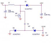
Are you doing a step up converter?
If so, see tha attached drawing. Adding C2, C3, D2 and D3 to a standard boost converter creates a negative output. While this output is not regulated, it is relatively predictable. If the positive and negative currents are the same, this also counteracts some of the errors.
Alternatively, the Maxim MAX629 can be used. Use one for the step up, and one for the inverter. See the datasheet.
For your applications, set SMPS to 14.5 or so. I checked the LM79L12 datasheets, it has a typical dropout of 1.6V with a 40mA load current. Use an LM78L12 for the positive.
Attachments
Nice pcb but a bit odd to have such a mix between SMD and holemounted parts, especially the LT1115.Paul Ranson said:The Dynavector P75 phono stage uses an internal SMPS working from an external 12v wall wart. FWIW.
There's an internal photo at http://gallery.photo.net/photo/3920485-lg.jpg
Paul
Hi speaker Guy,
That schematic looks so simple.
Am I reading it correctly?
C2 sucks energy out of the ground and sends it to be stored in C3 for -ve rail use!
That schematic looks so simple.
Am I reading it correctly?
C2 sucks energy out of the ground and sends it to be stored in C3 for -ve rail use!
Re: dual SMPS
not what I would call a low-noise circuit -- btw, some folks have used RS232 converter chips (max232) to derive +/- 18 V -- but noisy!!
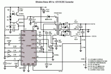
here's an example of a low noise bipolar supply:
thespeakerguy said:Are you doing a step up converter?
If so, see tha attached drawing. Adding C2, C3, D2 and D3 to a standard boost converter creates a negative output. While this output is not regulated, it is relatively predictable. If the positive and negative currents are the same, this also counteracts some of the errors.
Alternatively, the Maxim MAX629 can be used. Use one for the step up, and one for the inverter. See the datasheet.
For your applications, set SMPS to 14.5 or so. I checked the LM79L12 datasheets, it has a typical dropout of 1.6V with a 40mA load current. Use an LM78L12 for the positive.
not what I would call a low-noise circuit -- btw, some folks have used RS232 converter chips (max232) to derive +/- 18 V -- but noisy!!
here's an example of a low noise bipolar supply:
Attachments
- Status
- Not open for further replies.
- Home
- Source & Line
- Analogue Source
- SMPS for RIAA


