Hi all,
please redirect me if this topic has been discussed elsewhere. I am attempting to use a single relatively robust 24V 16A SMPS to power 6 class D amp modules for an active 3-way speaker pair. I have the 6 200W amps connected in parallel to the PS, and they have modest duties, as are my listening levels. (I calculate that I will not be generating more than 30-50 W from the whole thing at peak moments.)
Each amp performs satisfactorily when (all powered up together) one source is connected at a time to each. As soon as a second source is connected I get lots of noise, especially around 1.2 kHz. I get similar results when the 24V output is floating or when the -24V rail is tied to earth ground. The power ground input (- dc rail) and source input ground are common on the amp boards. So far I have only used an ipod (not connected to earth ground) for test signal.
Although it is likely I am doing something fundamentally wrong here, I wonder if I am on the right track suspecting the parallel power distribution to be a concern. I read that some SMPSs are "synchronized" for use with multiple loads, one being a "master." Being a novice with switchmode tech, I was naively hoping that I could use this unit as I have linear PSs I have built before for similar active C/O projects.
Here are links to the units:
https://store.sure-electronics.com/product/AA-AB31282
https://www.meanwell-web.com/en-gb/ac-dc-slim-single-output-enclosed-power-supply-uhp--350--24
Having probably neglected some important info, I welcome questions, comments, and advice. Thanks
Gary
Last edited:
just do it....6 x 200 watts is 1200watts, your psu 24v x 16A is just 384 watts, clearly short of 1200 watts...
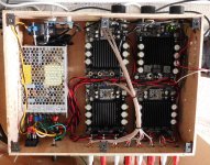
Sure you can, and I do something very similar (see pic). I don't need much power either, so I have an undersized power supply as well. I have had noise problems due to poor grounding and ground loops but those are separate issues from the Amp/PS.
You can do a few simple tests to find where the noise may be coming from. These tests are for only the power supply and amplifiers, no other equipment should be connected. I'm assuming you have a proper "star" wiring distribution from the PS (V+, V-) to the Amps.
First, short an amplifier signal input to gnd (V-), and if you still get noise (use a full range or woofer), it could be the power supply or the amp itself.
Second, if you had noise one one amp, try shorting the input of another amp board and if you still get noise its very likely the power supply.
[edit - more specific on inputs ]
Attachments
Last edited:
Thanks for the replies. To make for cleaner wiring I ran power to each amp in a daisy chain, with the thinking that each of the 6 + and - amp nodes “see” the respective 24v and 0v PS outputs. See attached. Would it be better to star groun as in the second attachment? Besides the possibility of a slight voltage drop at peaks, what other issues does the chain introduce? And thanks again for the help.
Attachments
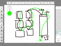
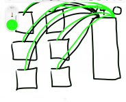
Using the star arrangement (pic#2) ensures equal V+ current and V- return current in each wire segment to each amp. The equal V+, V- currents create equal B-fields that mostly cancel each other (less radiation). Using a wire pair, or twisting the pair ensures minimal loop area so it radiates less and is less susceptible to interference (radiation reciprocal). A grounded shield on the power pair would be even better, but I did not require it,
The daisy chain has incrementally more current in each segment (closer to supply) and it will not be balanced (equal current in V+, V- of each segment). There may also be some common mode modulation from the wire impedance that may appear as supply variation at the amp supply terminals. This is not a DC resistance V drop, it is AC modulation from wire impedance. The T amps switching freq varies between 100Khz - 1Mhz and it's load dependent.
If you short the input terminals to all the amps, do you still hear noise on the speaker?
[edit] - I have 3 stereo (2x100w) T-amps and 1 mono (1x200w) T-amp in the pic above. I have removed the RCA jacks and replaced them with terminal blocks to make internal wiring easier. I also removed the small amp fans and used a larger single variable speed case fan.
Last edited:
Hi Don, I will re-wire using the star arrangement. It sounds like this is a no-brainer as it addresses several potential and actual problems at once. (Just doesn't look as tidy.) I made shorting plugs for each amp input. Same result, as soon as a second source is added, that shares a common ground, using any pair of the amps, I get this noise, (most audibly 640 Hz.) So I connected instead, 2 separate input sources, (iPod and cell phone) neither connected to ground, and the noise is gone, both channels sound fine. This repeats with any combination of amps.
I will report back after re-wiring, but I will eventually need to have all inputs referenced to ground as they will all be going to a DXO. Thanks for the help and talk soon.
I will report back after re-wiring, but I will eventually need to have all inputs referenced to ground as they will all be going to a DXO. Thanks for the help and talk soon.
Typically all the input channels are from one piece of equipment (eg. DXO). You also need them all to be single ended.
What is unusual, is that your 2 sources are battery powered and effectively floating. It is possible that one or more outputs are differential and not single ended (you require single ended for direct connection) so the sources are interfering with each other.
One additional detail about the T-amps. The outputs are differential (PBTL) and with shorted inputs, both output terminals (out+, out-) will be at the supply voltage V+ (ie. difference=0). Do not connect any outputs together from different boards.
Perhaps the switching frequency of your amps is depending on signal strength. In that case, feeding a signal to more than one amp might bring the switching frequencies in the same ballpark. When fed from a single ps, the result is that both slightly different switching frequencies will start to beat. This can create noise at audible frequencies.
Some class d amps can be put in slave mode to align their switching frequencies. If not and the problem occurs, only using different power supplies for each amp one might help.
Some class d amps can be put in slave mode to align their switching frequencies. If not and the problem occurs, only using different power supplies for each amp one might help.
OK, 24V * 24V/8 Ohms/2 = 72Watts max per channel * 6 channels = 432 Watts total so you are probably fine. This assumes the amps are all bridged and driving 8 Ohms. Double that power if your speakers are 4 Ohms, but 1/4 if the amps are not bridged. You will want to include some bulk storage caps so that peak currents are averaged out.
You probably have grounding problems. Power supply ground and input grounds should not mix on the amp boards. The input grounds should be wired together and connected to ground at the power supply. I assume by "-24 rail", you mean zero Volts and not two 24V split supplies?
You probably have grounding problems. Power supply ground and input grounds should not mix on the amp boards. The input grounds should be wired together and connected to ground at the power supply. I assume by "-24 rail", you mean zero Volts and not two 24V split supplies?
I was puzzled why I had +12 volts from each speaker output to ground, and the differential design explains that.. Steve, you are right, I meant negative rail, or 0 volts, not -24. The negative terminal of the PS is star grounded (see attachment above).
I read a little about slaving, I think the term synchronized was used, but I doubt I have the budget or space for an esoteric piece of gear to do this. Does anyone know how this would be best done in a hifi context?
I did not bridge any of the amps, each powers one channel of a stereo WMT pair of loudspeakers (arrays this time). Maybe you are referring to their design Steve? And for bulk storage a simple RC network? 20-50,000 uF?
I will try to re-wire the amp tonight and see if this fixes it. Any other suggestions? If this does not help, I may order 6 of these instead, I think they'll fit but it will be tight:
https://www.trcelectronics.com/View/Mean-Well/EPS-65S-24.shtml
Take a pause to further diagnose the problem, as you have not identified the root cause yet. The 6 supplies are not required. The T-amps cannot be synchronized, each modulator will vary the freq and duty cycle depending on its input levels. If a large capacitor bank is added it may cause fold back current limit on supply startup and the supply will "hick-up" if it does not have a sufficient slow start circuit.
The fact that you have used 2 battery powered devices (Ipod, cell phone) and they work properly (no noise) is a strong hint that the noise is not inherently from your power supply or amp. It's more likely that the "other" 2 source devices were causing a grounding or ground loop issue. What are the "other" 2 source devices and are they just for test or intended actual use?. How were they powered and connected to the T-amps?. Simple sketch is enough.
[Edit] are you still intending to use a single DXO as a source for all of the T-amps?
Last edited:
Don, I think you are correct that the issue does not originate with the PS. I disconnected the chain (attachment 1) and configured 2 channels only using power connections direct to PS (attachment 2). No change. I then connected each of 2 amps to their own individual 24v SMPS and now I get double/stereo noise in a distinctly unharmonic cacophany. Level is about the same. Again, this is only when the two channels share signal ground via 1 input source, ipod.
You are correct that ultimately I intend to supply all amp inputs from 1 DXO (Behringer DCX2496). So, yes, The inputs will need to reference the same 0 volt signal ground, probably star connected to safety ground at AC socket. I have learned to do this at only one place in order to mitigate loops…as yet, none of the input grounds are connected together at the jack, but as mentioned, each amp shows continuity between 0vdc in and signal ground in, so it is happening on the board.
I will sketch and post my configuration and test conditions shortly…thanks
You cannot bridge amplifiers that are already bridged. They have to share a common ground/speaker return. The negative outputs of your amps are hot, an inverted voltage wrt the positive outputs, not ground. If you connect two negative outputs together, that would just short them out. All outputs must average the middle of the supply, which in your case is 12V, half the 24V. The two 12VDC cancel/match so that there is no DC across the speaker. You cannot get negative AC swing wrt ground without a negative power supply.
Bulk storage is just a capacitor (bank) across the 24V. And R would be a mistake. Perhaps a cap on each module would work well so that speaker (AC) current is mostly local and little has to come from the power supply.
A class-D amplifier dumps current from one supply (positive/negative) to the other, but a bridged output dumps both ways at the same time, cancelling so it's not a problem. Or in this case, there is only one supply.
If your amplifier modules connect the input ground to the negative rail on the PCB, you may have to cut a trace and reconnect externally to the PS, so that the supply noise does not get into the input ground. We cannot be there to reverse engineer your boards, so you have to gain an understanding of grounding yourself. No wire carrying speaker current can be part of the input circuit, ie ground paths cannot be shared. The input and output current loops can only connect at a single point.
Last edited:
Hi Steve, thanks for the insight. I am doing my best to digest it. First response is I have no intention to bridge any pair of these amps so that issue is averted. No speaker terminal will be connected to any other. If I understand you correctly, the T-amp circuit is inherently a bridged design in which the speaker midpoint is at half the supply voltage, in my case 12 volts…? 12 of those volts facilitate the push of current one way and 12 of those volts facilitate the pull of current the other way. Which would mean signal ground can never be shared between amps because they each determine where that point is depending on what the input signal is doing at any given moment. I’m totally confused. I have built many amps, all enjoying a positive and negative supply with 0 in the middle as an impartial referee. I need to search for a visual aid to help me relearn what is going on here with class D.
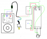
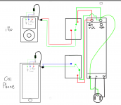
While I do, and reread recent posts, I am attaching diagrams of my 2 successful and ultimately useless configurations, and one showing the problem, which I suspect you already understand and I don’t. Yet.
While I do, and reread recent posts, I am attaching diagrams of my 2 successful and ultimately useless configurations, and one showing the problem, which I suspect you already understand and I don’t. Yet.
Attachments

1 - how are you measuring the frequency of the noise?
could you be an order of magnitude out?
60 Hz (rather than 600Hz) would suggest a ground loop.
2 - move the power supply away (long cable on LV side). If this reduces the noise then radiated noise from PS is the problem.
3 - diag 1 (noisy), what happens if you disconnect blue, leaving both green input grounds connected?
4 - diag 1 (noisy), what happens if you disconnect green input ground from second amp, leaving blue connected?
Thanks for the sketch.Hi Steve, thanks for the insight. I am doing my best to digest it. First response is I have no intention to bridge any pair of these amps so that issue is averted. No speaker terminal will be connected to any other. If I understand you correctly, the T-amp circuit is inherently a bridged design in which the speaker midpoint is at half the supply voltage, in my case 12 volts…? 12 of those volts facilitate the push of current one way and 12 of those volts facilitate the pull of current the other way. Which would mean signal ground can never be shared between amps because they each determine where that point is depending on what the input signal is doing at any given moment. I’m totally confused. I have built many amps, all enjoying a positive and negative supply with 0 in the middle as an impartial referee. I need to search for a visual aid to help me relearn what is going on here with class D.
While I do, and reread recent posts, I am attaching diagrams of my 2 successful and ultimately useless configurations, and one showing the problem, which I suspect you already understand and I don’t. Yet.
It's unusual to have a ground issue when using a battery powered floating device like an iPod or a phone. There is a strong hint that the connection from the iPod has a problem. Apple products have various jack pinouts and often use 4 pin TRRS, and not the standard 3 pin TRS. Even the pin assignment can be different depending on the model. The iPod shuffle uses the TRRS for battery charging as well (uses a 4 pin TRRS to USB cable).
Which model and generation of iPod is it?
Can you use 2 channels (LR) from just the Phone connected ? or is it the same as the iPod.
Last edited:
Responding in reverse order: Don, I swapped out the iPod of the cellphone only and got the same results. So unless they both share this connection issue, unlikely the culprit. It is an iPod Classic 160 GB.
Russc: 1. The frequency of the noise was measured two ways. The audible manifestation was simply compared to a tone generator. As mentioned before, the frequency declines over time. (When I first meaured it was at 666 Hz! Over twenty minutes it had fallen to 620 Hz.) I just recorded an mp3 of it on my phone, but realized it isn't allowed. (Are there any audio file formats allowed?) I got the 1.2kHz from an oscilloscope, which shows it also.
2. I will have to do this later as it will require much disassembly, and I only want to do that once other simpler diagnostics are considered, like your others...
3/4/5. Baseline reading on my dBv meter 6" from speaker is 36 (no noise condition). The noise condition shows a roughly equal 52 dBv on each side. When second channel (R) signal is connected only, R ground dangling, I read 70 dBv on the L channel. When I connect second channel ground only, Signal dangling, I read 50 dBv on the R channel only. When L signal only is sent to both amps, same noise as before.
Thanks for lending your minds to this. I have been reading about class D and apparently there are often multiple opamp stages in which the signal is inverted, buffered, summed, etc., and so far I have yet to see a design without negative feedback. It is a really cool idea. I cannot accept that a class D amp cannot share a signal ground with another class D amp, so I will keep trying...
Was it the same cable that was used for the iPod? Do you have another ?
I use 1 supply with 3x Stereo+ 1xMono T-amp boards with a single ground, no problems. I also connect it to either a PC sound card or an active analog XO and no problems. I have an active 3way horn system. It can be done.
I use 1 supply with 3x Stereo+ 1xMono T-amp boards with a single ground, no problems. I also connect it to either a PC sound card or an active analog XO and no problems. I have an active 3way horn system. It can be done.
- Home
- Amplifiers
- Power Supplies
- SMPS for multiple amps?