I can make a 1000 watt supply for an amplifier just by buying a 1500VA toroid, 50 amp bridge rectifier and two 22,000 uF caps (and maybe a thermistor, and 15 ohm resistor and a .01 uF x-cap for the snubber if it needs it). Plug it in, turn it on and it works. No ifs, ands or buts. That supply can be loaded with 5000 watts average (with pi times that in peaks occurring every 50 milliseconds) during sine wave testing at low impedance at low frequency repeatedly over the course of several minutes - without going into hiccup mode. Try doing that with an SMPS for *any* reasonable amount of money, not to mention the 10 iterations over a year’s development time with many blown IGBTs along the way getting there.
++1 😉
@tubelab_com that looks and interesting project 600+V and 1KW looks more like interleaving or full bridge......A x kW pfc will get you to 390V typically, then it’s really just adding after. Only issue is the smell of expensive switches going pop ��
Most if not all PFC's are not isolated, therefore whatever comes after the PFC must be isolated.
600V 2.5KW using GANFET eval board: https://www.mouser.co.uk/datasheet/2/970/dhbg2500p100-user-guide-20171206-1539032.pdf
Shouldn't be too difficult to make one using the 900V GANFET rather than the 650V they use.
That design is also not isolated from the power lines.
SMPS can be sensitive.. GANs in a bridge mode need careful design,
GaN needs care....PERIOD. Gallium Nitride devices are quite prone to secondary breakdown. This is not usually an issue in switching applications, which is where most GaN is used.
I spent over a year of my 41 year engineering career working with the component vendor on random failures in a 90 watt 2 GHz GaN fet device designed for pulse mode. We were using them in a 5 watt continuous operation application. After months of taking video through a Flir camera with an $18,000 lens mounted on a granite block capable of shooting IR video in full frame format, I managed to capture a couple breakdown events. I was offered a buyout and left the company before that was all sorted out, but the product is now shipping about 4 years later.
The key to making a quiet reliable SMPS lies in the transformer. By experience with DIY SMPS transformers have all led to exploding mosfets.
I got a big box full of the 48 volt 3 amp supplies I linked to for under $15 each. I bought 5 first, and they all survived load testing when wired in series, so I ordered more. The nest step is 13 in series.
An in case it matters, I have two Tektronix CRO's and one Rigol LCD.
Most if not all PFC's are not isolated, therefore whatever comes after the PFC must be isolated.
Indeed, you can put a 1:1 isolation transformer before them but isolation in the SMPS frontend supply to the loads also isolates from problems and makes it easier to reference.
I'm just looking at a the frontend power - class A but +320 and -200 rails, an isolated Cuk off the PFC DC link. I figured that isolated, apart from the obvious safety aspects also means the noise can be on both rails for cancellation.
That design is also not isolated from the power lines.
All reports, Ganfets seem quite fragile, needing a lot of baby sitting - sort of thing I'd leave alone.
GaN needs care....PERIOD. Gallium Nitride devices are quite prone to secondary breakdown. This is not usually an issue in switching applications, which is where most GaN is used.
I spent over a year of my 41 year engineering career working with the component vendor on random failures in a 90 watt 2 GHz GaN fet device designed for pulse mode. We were using them in a 5 watt continuous operation application. After months of taking video through a Flir camera with an $18,000 lens mounted on a granite block capable of shooting IR video in full frame format, I managed to capture a couple breakdown events. I was offered a buyout and left the company before that was all sorted out, but the product is now shipping about 4 years later.
The key to making a quiet reliable SMPS lies in the transformer. By experience with DIY SMPS transformers have all led to exploding mosfets.
I got a big box full of the 48 volt 3 amp supplies I linked to for under $15 each. I bought 5 first, and they all survived load testing when wired in series, so I ordered more. The nest step is 13 in series.
An in case it matters, I have two Tektronix CRO's and one Rigol LCD.
Parallel and/or interleaved then.
Only issue I have with stacked isolated SMPSs is current sharing.
Till now I got many fire trainings and I alway learn 4 families die every month because of wall warts or phone chargers catching fire. Just that fact is enough to NOT want stuff plugged in under voltage 24/7...
I used to snowboard with a mathematician that did insurance modelling. Turns out 7 people a year die from attempting to put their socks on whilst going down the stairs. So I'm sure crap chargers are adding more to everyone's premiums than the energy they save. Don't get me started on diesel..
Just need to look at the large supplies for MRI machines: US8829905B2 - Magnetic resonance imaging compatible switched mode power supply
- Google Patents seems SMPS is still favoured.
The acquisition cores are run with linear LDOs but in the end they have considerable post processing to remove noise.
A 2KW isolation transformer defeats the purpose of the SMPS, which is for putting the entire amp on a weight loss program.
I already have some 600 VA 4 winding toroidal isolation transformers. The easy solution, and one that I have tested is to put a bridge and big cap on each 120 volt secondary, then wire 4 of the resulting 150+ volt supplies in series. That gets me about 670 volts unloaded, 655 volts with one channel idling, and 630 with one channel at full power just over 500 watts output. It would take 4 such transformers plus heater power to power a 1KW amp. Each transformer weighs just over 12 pounds. Each OPT weighs 18 pounds.
I have been grabbing scrap stuff from an MRI machine repair company at the Dayton Hamfest when they bring it.
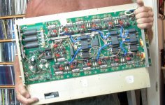
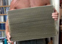
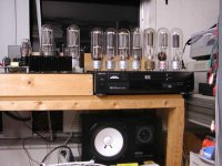
I bought this 2.5 KW MRI amp for $50 several years ago. I wanted the RF power fets and the ferrites for ham radio power amps. I separated the PC board from the big heat sink, and took the RF stuff I wanted. I then resold the big heat sink to a guy that was building a big class A audio amp for almost as much as I paid for everything.
There was a 48 volt 1KW SMPS and a few BIG caps that dealt out the power pulses for the 2.5 KW RF amp. That power supply is now running a TI TPA3255 EVB to slap around a Dayton subwoofer from Parts Express.
I already have some 600 VA 4 winding toroidal isolation transformers. The easy solution, and one that I have tested is to put a bridge and big cap on each 120 volt secondary, then wire 4 of the resulting 150+ volt supplies in series. That gets me about 670 volts unloaded, 655 volts with one channel idling, and 630 with one channel at full power just over 500 watts output. It would take 4 such transformers plus heater power to power a 1KW amp. Each transformer weighs just over 12 pounds. Each OPT weighs 18 pounds.
Just need to look at the large supplies for MRI machines:
I have been grabbing scrap stuff from an MRI machine repair company at the Dayton Hamfest when they bring it.
I bought this 2.5 KW MRI amp for $50 several years ago. I wanted the RF power fets and the ferrites for ham radio power amps. I separated the PC board from the big heat sink, and took the RF stuff I wanted. I then resold the big heat sink to a guy that was building a big class A audio amp for almost as much as I paid for everything.
There was a 48 volt 1KW SMPS and a few BIG caps that dealt out the power pulses for the 2.5 KW RF amp. That power supply is now running a TI TPA3255 EVB to slap around a Dayton subwoofer from Parts Express.
Attachments
I grew up in Miami Florida in a time when only rich people had air conditioning, and we were not rich. There was also a lake nearby and I spent quite a bit of time in it....or the Atlantic Ocean for that mater. For most of my life I wore just a pair of shorts unless more clothing was required. So did most of my friends.
I lived in south Florida for 62 years, and spent much of my time outdoors and in the water, so that habit is still with me even when nobody is around and it is not so hot now that I have moved 1200 miles north.
I lived in south Florida for 62 years, and spent much of my time outdoors and in the water, so that habit is still with me even when nobody is around and it is not so hot now that I have moved 1200 miles north.
Sorry, old fashioned person here. Had to wear a shirt on pictures and dinner without t-shirt meant no food (whatever the temperature was) 🙂
But ... are you seriously openly admitting you are using a class D amplifier? 😉 You know this will be filed don't you?
But ... are you seriously openly admitting you are using a class D amplifier? 😉 You know this will be filed don't you?
Last edited:
But ... are you seriously openly admitting you are using a class D amplifier? 😉 You know this will be filed don't you?
I built tube amps as a kid because tubes and parts were available often for free in discarded electronics. I got a job at Motorola in 1972 and silicon was free just by filling out a sample request form, so I built mostly solid state stuff from the 70's through the mid 90's.
Somewhere in the late 90's I traded a broken car for a broken Scott tube amp which I fixed. Within a few months that amp has pushed all of my Carver / Phase Linear solid state stuff out of the rack in the living room. That system has been all tube ever since. The 15 inch OB speakers do not need any help in the bass department, and a Tubelab SSE tube amp makes them plenty loud. I gave all the SS stuff to a friend when I left Florida in 2014 after taking a buyout from Motorola.
I had a DIY solid state amp in my lab / work room / home recording studio in Florida. It was a tiny and hot 100 Sq Ft (about 9 sq m) room where I did everything from rebuilding car engines to making computers and amplifiers to recording music. There was only room for one audio system, and it was always changing. In the late 90's I replaced the solid state audio amp with a DIY KT88 based tube amp. As I transitioned from tape based recording to PC based digital the Teac 3340 was sold, and in my stupidest move I sold all of my 70's and 80's vintage analog music synthesizers and bought "modern" digital stuff, which has all since died.
Somewhere in the 2000's I added a $200 mail order active sub with a class AB solid state plate amp inside to my home studio setup in Florida. It handled the frequencies below 100 Hz where my Yamaha NS-10M Studio's or FH-3's have no output. One of several tube amps provided all the sound and music. In the small room everything worked good together.
In 2014 my engineering career came to an end, and I moved 1200 miles north and my lab / work room / listening room is now a 1600 sq ft basement. There are two complete audio systems and several test systems.
The one used mostly for listening to music is all tube from the turntable to the DIY speakers. I can also play music from the PC or DVD player and I have ripped most of my CD's to the hard drive. I have even digitized some of the records to the hard drive.
There is a second system that is mostly used for video editing and music recording, experimentation and computer based music creation using a DAW (Ableton Live) and a mix of hardware and software music synthesizers.
The hardware synths are a mix of analog and digital, some commercial stuff, and some DIY stuff of my own design. A vacuum tube analog music synthesizer project has been going on for several years now. It is still far from finished.
The audio playback on that system is flexible and can be anything from all tube (class A UNSET to a class AB P-P amp of my own design, with or without the class d sub) to all solid state which can be all class D (powered speakers and the TPA3255 sub) or the class d sub and a class T chip amp. There are 3 speaker systems, a DIY MTM system , a pair of modern "self powered" studio monitors, and my old Yamaha NS10M studios because I know them well, I have used them in many systems since I bought them new in the early 1990's.
The cheap sub that I brought from Florida didn't cut it in this big room so I built a 4 cubic foot box with a 15 inch Dayton driver in it. I have tried several amps to drive it, including a Dayton plate amp. The sub doesn't need a lot of power since I don't play it loud, but it does need a low driving impedance (high DF), so most of my existing tube amps don't do well. The Dayton plate amp got pushed out by the TI EVB.
There was a thread discussing TI's own EVB's when they put them all on sale for half price. I can't find that thread now, but I bought a 600 watt 4 channel EVB directly from TI for under $100. It took forever for it to arrive, but it does a good job smacking the DIY subwoofer around. In reality I am only using 2 of the 4 channels in parallel and it probably only sees 50 to 100 watts on peaks. Some of my synths can go down into the deep bass region where the sub is needed, otherwise it's usually off.....unless Sherri is not home.
I will try some of my new tube amp designs when they are finished, but none of my cheap OPT's will do. I am also working on the 1 KW tube amp (500 WPC) that should do 400 watts at 20 Hz (the Plitron OPT spec). It could take over all of the audio duties on the second system given the right speakers.
The fact that some manufacturers sell a linear PSU as an upgrade for the switcher says at least something.
There are valid pros and cons, but these manufacturers would sell their own grandmother if they could make a profit from it.
Sorry, old fashioned person here. Had to wear a shirt on pictures and dinner without t-shirt meant no food (whatever the temperature was) 🙂
My wife (then girlfriend) complained once about me not wearing a shirt at the dinner table. I went to the bedroom grabbed a white tank top cut out holes to expose my nipples and returned to the table. She never complained about no shirt ever again.

As your sentence started with "my wife" I expected to read a female person also having dinner and walking around topless. I would not have a problem with that I think 🙂
Well executed joke 😉
I was just teasing, I use FDA myself and don't even bother to build stuff with tubes.
Well executed joke 😉
I built tube amps as a kid... TL;DR
I was just teasing, I use FDA myself and don't even bother to build stuff with tubes.
Last edited:
I was just teasing, I use FDA myself and don't even bother to build stuff with tubes.
I know, but there are still people here, and elsewhere who think it is a serious crime to allow silicon of any kind in the same room with a tube amp.🙂
Almost 20 years ago I built a tube amp known on the internet and some paper magazines as the "poor mans Ongaku." It is a big SE amp using an 845 tube on about 1000 volts. I believe it was sold in kit form or part by part from Audio Note UK. A coworker had purchased all the expensive parts, transformers, tubes, and sockets, but wandered off into the battery powered class A mosfet world before ever building it.
I built that amp, but did not like it. It measured bad (lots of IMD involving mains frequencies) and caused serious listener fatigue. I just got annoyed with it and wound up turning it off after an hour or so.
I ripped it apart and redesigned it into something I liked listening to. The redesigned amp had silicon in the signal path. The first two stages were on a PC board, a prototype of what became the Tubelab SE, and now the TSE-II.
I rarely used the 845 amp because it put over 500 watts of heat into my small room to make 30 WPC. After an hour it was too hot to be in the closed room, and I had two air conditioners.
The driver board went on to become a successful amp design using 45's, 2A3's or 300B tubes. When I first published the design on the internet the response was overwhelmingly negative. Several people even suggested that i change my name to Transistorlab. Now over 15 years later, sticking "sand" in a tube amp has become almost trendy.
I spent 41 years at Motorola, most of that as a product design engineer, or research engineer involved in "advancing the state of the art in radio frequency design." I will use the best part for the job, regardless of what it is.
I may be known here for abusing, and blowing up vacuum tubes, but the truth is that I have fried far more silicon, GaAs, GaN, and SiC in my life than vacuum tubes, and even got paid a nice salary for doing most of it!
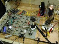
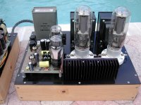
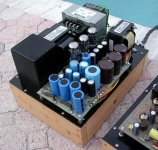
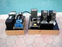
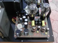
The first picture, almost 20 years old, shows the real early prototype. Yes, there is silicon on that heat sink. Its driving the big tube. The 5th picture shows the second prototype of a Tubelab TSE board being used as the driver in the finished amp.
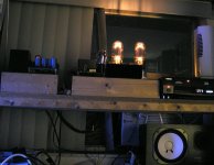
The finished amp sat up on a high shelf to minimize room heat. A window air conditioner can be seen below it (behind the speaker). It is one of the better sounding amps that I made, but still I only used this amp at night due to heat, and once I learned to build more efficient amps, not at all.
It's still on a shelf in the basement, but due to the presence of curious grandkids and exposed 1100 volts, it has not seen power in years.
Attachments
The key to making a quiet reliable SMPS lies in the transformer. By experience with DIY SMPS transformers have all led to exploding mosfets.
Which is why I don’t try to make SMPSs that can deliver 100 amp peaks like a regular core-coil supply can. A couple amps is easy. Gets harder and more likely to result in exploding mosfets with each zero you add.
I got a big box full of the 48 volt 3 amp supplies I linked to for under $15 each. I bought 5 first, and they all survived load testing when wired in series, so I ordered more. The nest step is 13 in series.
The biggest worry is capacitors (and capacitances) to ground. They won’t be expecting you to elevate it that high. You may have gotten away with with 5 if there are 250 volt caps hanging from either side to chassis ground. And high frequency currents may want to flow to chassis in places they shouldn’t through “unintentional” capacitors like from a TO-247 device tab to heat sink. Elevating voltages will increase the magnitude of these currents (and could result in exploding mosfets). I wouldn’t expect cheap supplies to be designed for high isolation. Might be able to make it so - at least you have some experience at high voltages. It’s a $200 experiment, and I’ve certainly thrown $200 at experiments that have potential savings.
Now, an $800 medical grade 48 volt 3 amp supply I would expect to work fine (even for powering a heater on a rectifier tube). But I would be seriously rethinking that weight loss program trying to buy 13 of them.
The biggest worry is capacitors (and capacitances) to ground. They won’t be expecting you to elevate it that high. You may have gotten away with with 5 if there are 250 volt caps hanging from either side to chassis ground.
Now, an $800 medical grade 48 volt 3 amp supply I would expect to work fine (even for powering a heater on a rectifier tube). But I would be seriously rethinking that weight loss program trying to buy 13 of them.
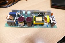
These are not the typical cheap power supply. They are "commercial grade" and still sold by Digikey for $160 each, even though they appear to be about 10 years old. They are "Made in Japan" and full specs and data sheets are downloadable. The isolation spec from any of the three possible combinations is 500 volts DC (which will be violated) and 500 to 3000 volts AC, the 500 volt spec being from output to safety ground (again, will be violated).
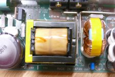
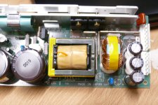
A full inspection of the board reveals the reason for the 500 volt spec. That brown capacitor in the upper right corner of the board goes from output to safety ground and it is rated for 630 volts. It will be removed. There is a nice wide isolation barrier between the input and output marked on the board. The only things that cross it are the optocouplers (2200 volt spec) and the previously mentioned cap.
The installation instructions state that these can be simply wired in series, but I'm sure that they didn't foresee the dumm blonde one wiring 13 of them in series, so I will include a big reverse biased diode across each output, and some higher voltage rated caps and inductors in an output network.
This series string of supplies will feed a bank of mosfets for choosing different plate and screen supply voltages, since I don't plan on running the amp at the 1KW power level most of the time. Provisions for shutting off some of the output tubes are an option too.
So here is another sin committed against the all silicon is evil in a tube amp crowd, this amp will have a 32 bit ARM core CPU watching over everything with full authority to cut power to prevent a nuclear meltdown. It will adjust bias and even test the output tubes too!
I stuck a DSP in a tube amp back in 2008 for a design contest in Circuit Cellar magazine. It won me some prize money, and a published article in the magazine, but got very little interest at the time, so I never pursued it further. It may be time to revisit the high efficiency class A / class H tube amp again. It will not happen in this kilowatt level monster, but more likely a 30 to 50 watt per channel SE amp.
Attachments
Wow, this is a project more than worthy of diyaudio motto: projects by fanatics, for fanatics.
Your avatar reminds me on the “Doc” from “Back to the future” and project fits the description.
I really like your signature line but sincerely hope that this project won’t live to it. 😀
Your avatar reminds me on the “Doc” from “Back to the future” and project fits the description.
I really like your signature line but sincerely hope that this project won’t live to it. 😀
Those look like really good supplies. Not particularly cheap, or light. How much weight does it actually save, 13 of those vs. 4 600 VA toroids? I have some 24 volt 10 amp units that are awfully similar (pulls from equipment) - and what did I do? Put 4 of them in series of course.
At least they *have* an isolation rating - which you’re not violating by THAT much. If you replace that 630 V (I’m assuming EMI suppression) cap with a lower value 3kV ceramic disc it will probably operate perfectly in a stack of 13. It’s not like some consumer garbage where they really only expected the output to be operated within 100 volts of ground, and running the power transistors on the ragged edge of destruction at full current rating.
One thing I would check is the peak current capability. I’m calculating you will need 3.6 amps at the top of the sine wave, and it looks like you’re interested in making this go down to 20 Hz. How far above the 3A rating can you go before it misbehaves? It may be ok at that quality level, but cheap supplies might not even give you that 20%. And in your typical class D junk, the manufacturer probably wouldn’t oversize the supply by 80% to begin with, and limiting problems would happen a whole hell of a lot sooner.
And for anyone who cannot do simple math, George is proposing using a power supply solution that is supposed to cost TWO THOUSAND DOLLARS. It looks like it is up to the task, and unfortunately that is WHAT IT TAKES to make this happen.
Those look like really good supplies. Not particularly cheap, or light. How much weight does it actually save, 13 of those vs. 4 600 VA toroids?
One thing I would check is the peak current capability. I’m calculating you will need 3.6 amps at the top of the sine wave, and it looks like you’re interested in making this go down to 20 Hz. How far above the 3A rating can you go before it misbehaves?
Each power supply weighs 1.04 pounds on the same scale that weighed the 600 VA toroid at about 12 pounds. 4 of those plus the OPT and the chassis (probably a rack mount server chassis or an old vacuum tube power supply chassis) makes this amp a boat anchor that I can't move. A friend gave me a 1KW RF amp for 432 MHz. It's still sitting where two of us left it.
I tested one and it I limits at just over 3.2 amps. I may be able to mess with a resistor value and get a bit more if I can find the spec on the Mitsubishi chip it uses. Repeated abuse or dead shorts cause shutdown. Once the first supply shuts down.....
I have bench tested one half of one channel here in post #56
UNSET is coming?
I saw 750 mA at 250 watts with a 2500 ohm load. The final amp will be two or three of those in parallel through the same OPT at 1250 ohms. Yes, it will draw a bit more current at 20 Hz, so I might not get 500 watts continuously at that power. I will be sensing the screen grid current and throttling the drive to avoid "undesired events" if the amp is ever driven to hard clipping.
Do I need 1KW at any frequency? NO, this is one of those "I built it because I can" things.
I have been talking about a vacuum tube kilowatt for about 10 years, I need to build it before I get too old to move it!
I was calculating peak current draw based on two channels putting out 500 watts each into 312.5 ohms. Average is lower, but SMPS limiting circuit time constants are usually shorter than 50 milliseconds. Which is why amps like the Crown Xti1000 suck as subwoofer amps (well documented case). At 3.2 amps you’ll still get close to full power at 20 Hz. It’s not like it will start misbehaving the instant you go over 200 real average watts.
No one “needs” a kW at any frequency. Even DJing you can “get by” with two cute little 200 watt plastic speakers on sticks. I tend to like it a little louder than that (by 10 to 20 dB), with bass that can get into the low 30’s. It sounds better that way. For a tube amp, A kW would be a good benchmark - bigger than one of the ones they were using at Woodstock.
No one “needs” a kW at any frequency. Even DJing you can “get by” with two cute little 200 watt plastic speakers on sticks. I tend to like it a little louder than that (by 10 to 20 dB), with bass that can get into the low 30’s. It sounds better that way. For a tube amp, A kW would be a good benchmark - bigger than one of the ones they were using at Woodstock.
- Home
- Amplifiers
- Power Supplies
- SMPS for Hi-Fi?