Hi to all,
I am making this SMPS (figure 9.) for car sub amplifier. My first block - control cirtuitry is completed and tested. But i have some questions.
I am using not SG3525A but SG2525A. In the datasheet i found that they are absolutely identical, except operating temperature for SG2525 is -25 to 85 and for SG3525 from 0 to 70. But i am not sure about the output logic. Datasheet says - "The
SG3525A output stage features NOR logic, giving a
LOW output for an OFF state" Maybe SG2525 outputs operates different? Must i get exactly 3525 chip for this project?
Chip operates from 12V source and consumes 16mA of current. Slow start works very nice. After power turning on, pulses are slowly groving to its normal size in about 2-3 sec.
I watched with osciloscope at the outputs. The High output is 8us and the LOW output is 10us. So if i am right my oscilator works at about 55kHz. But i am afraid about this difference in duration of LOW and HIGH outputs.
In the project description there is 12k ohm resitors , mine is 11.9k ohms. Maybe this caused such problem? Or anything else?
I am absolutely not strong in this stuff, so your help will be really appreciated.
Thanks to all , and sorry for my bad english.
Both chips are interchangable....but for the operating temp.
THe difference in pulse width is due to dead band,Dead band can be minimal if using MOSFETS ....by reducing Rd between Ct pin and Rd pin ie Pin 5 and Pin 7,........Try 47 Ohms..
PS: Not seen the circuit u mentioned.
Good Luck
Sivanand
THe difference in pulse width is due to dead band,Dead band can be minimal if using MOSFETS ....by reducing Rd between Ct pin and Rd pin ie Pin 5 and Pin 7,........Try 47 Ohms..
PS: Not seen the circuit u mentioned.
Good Luck
Sivanand
the circuit:
Thanks for suggestion. I will try smaller value of R8.
An externally hosted image should be here but it was not working when we last tested it.
Thanks for suggestion. I will try smaller value of R8.
So i have just changet the resistor for smaller one, and now the dead time is shorter a bit.
I connected switching transistors ant transformer and this is how looks my secondary windings waveform:
wave form
main pulse is about 40V but that spikes up to 120V looks to me not very nice
I measured with no output diodes and capacitors and no load. And wires between transistors and transformer was long (~20cm) and thin. Maybe this causes such result?
Where can i look at right smps waveforms?
Thanks again.
If therez too much spike...reduce stray inductance in the circuit,ie the lead connecting mosfet drain to tranf should be minimum,not more than few cm,practically posible,If using PCB try few parallel tracks 3#.
R15 and C15 should be there,will reduce overshoot!!!
GOODLUCK!!
Sivanand
R15 and C15 should be there,will reduce overshoot!!!
GOODLUCK!!
Sivanand
so, i am back again
I just have rewinded my transformer, now on two glued ferite rings, each inner diameter 29mm , outer diam. 45mm and cros-section 0.65 cm^2. Three enamelled copper 1.5mm diameter wires in parallel form primary - four turns - center tap - and another four turns in the same direction. Then the secondary over the primary in the opposite direction, with two 1.5mm diameter wires in parallel - eight turns -center tap- another eight turns in the same direction.
I connected my setup again - control circuitry with BD139-140 , switching mosfets IRF540 and transformer. Suply voltage 14V. Current from suply is about 0.2 A. Is this normal?
And after 10 min. transformer becomes markedly warm. Not hot, i can hold it easy with fingers, but warm. Must it be warm without any load, even without diodes and capacitors ?
I am sligtly worried about this, maybe i must rewound my transformer in different way?
Thanks for help.
I just have rewinded my transformer, now on two glued ferite rings, each inner diameter 29mm , outer diam. 45mm and cros-section 0.65 cm^2. Three enamelled copper 1.5mm diameter wires in parallel form primary - four turns - center tap - and another four turns in the same direction. Then the secondary over the primary in the opposite direction, with two 1.5mm diameter wires in parallel - eight turns -center tap- another eight turns in the same direction.
I connected my setup again - control circuitry with BD139-140 , switching mosfets IRF540 and transformer. Suply voltage 14V. Current from suply is about 0.2 A. Is this normal?
And after 10 min. transformer becomes markedly warm.
Not hot, i can hold it easy with fingers, but warm. Must it be warm without any load, even without diodes and capacitors ?I am sligtly worried about this, maybe i must rewound my transformer in different way?
Thanks for help.
Waveform
DT,
WOW! That's alot of ringing. I'm glad you're using the IRF540s, because at 100V(ds), you will need it. As for core saturation (presumably from MOSFET imbalance), as long as the MOSFETS came from the same production batch, you should be OK. This is indicative if the date codes on the individual MOSFETs match. Better yet, try hand-matching them. Set up a test rig, where you measure the V(gs), as the I(d) goes up. Measure these curves to within 0.5mA (500uA), and you should be good.
The SG2525 is the industrial version of the SG3525. If you're fortunate to get any SG1525s, you have the military version. These have storage temperatures ranging from -65 Centigrade to +150 Centigrade, and an operating temperatures ranging from -55 centigrade to +150 Centigrade. Great for those Baltic winters!
Anyway, you should not measure the MOSFET wavefroms with the outputs unloaded. SMPSs don't like to run without even a minimum load, because the very narrow pulses at light (or no) loads will produce alot of spike-like ringing. Loading the outputs with +/-100mA of current should do the trick. If this doesn't work, try playing with the RC snubber component values across the transformer's primaries.
Are you regulating the outputs, or are you running at max duty cycle (minus the deadtime)? Also, you could try putting a common-mode choke (wound on a powdered-iron toroid core) in line with the outputs for smoother filtering.
Please let me know, as I have made a Switcher like this, only with output regulation, and it works very well. And, if I could figure out how to compress the pic file small enough, I would post it here. The power supply I made comes from Audio Amateur magazine from the last issue of 1989 and the 1st issue of 1990 (it was a two-part article), out of Randy Vikan's 75W + 75W MOSFET car amp.
Best of luck,
Steve
very thanks to all for answering, i am just beginner in this stuff, so your help is very appreciable.
I will try to make another transformer with few thinner wires. But dont know how to check primary current waveform , and how to realize that core is saturating or not
To my this is a little painy, because i dont own an osciloskope, i can just borrow it. Maybe one can explain to me how to check saturation?
I even dont know the procedure of hand matching the MOSFETS ...
There is no SG1525 in our local stores, but 2525 i think must work pretty well too.
My SG2525 operates without regulation, exactly like here, just in the place of R3-R4, R5-R6 22Om i am using BD139-140 with 10Om and 2.7Om resistors to switch MOSFETS. With sthese small transistors there is less ringing in square waveform than with only SG2525 outputs.
I will try put some load on output and then measure all again.
Steve, to make the pic file smaller you can use any graphic program and resize it. Just in case of Windows Paint : Opent the file, then press CTRL+W (Menu Image-Stretch/Skew) then in the Stretch in horizontal and vertical positions you can change the value of 100% to smaller one. And after saving this you get smaller file.
lots of reasons for the ringing -- the generic values for the snubbers on the switching side, or on the secondary rectifying side may not be correct. the values are going to depend on the inductance of the transformer and the transistors. OnSemi has some good materials on snubber design in their big diode handbook, and it is a long and tiresome discussion...
you might want to try various output choke values -- make sure that the supply is loaded, with the minimum supply current which the chip is going to draw -- you can start with 100uH.
if you have the magnitude of ringing which was exhibited it will also migrate back to the battery terminals -- a 200uH choke here is also a good idea.
It seems that this huge ringing was due to unloaded transformer.
I connected some resistors to form load of 45mA for + and - , so 90mA total.
Output voltage is about +- 24-25V, i think is very usable for paralleled IGC 2 x LM3886. Or must i go higher?
For testing purposes i put only 100mF capacitors on each rail.
There is some oscilograms, how things look like:
Output from BD 140-139
Between secondaries i connected RC circuit 220R + 1n.transformer primary and secondary waveforms
DC with 100mF and 90mA load
Better Waveforms
Dainius-
These waveforms look much better. By the way, the 35A 200V ultrafast bridge, is this a diode bridge in a single package, or are these 4 separate discrete diodes?
I have been looking for an ultrafast bridge for a while now, and have never been able to find one. if I can get away from separate discretes, that would be great!
Keep us posted on your progress, and later today, I will dig up the SMPS pic(s) I promosed and upload them here.
Steve
Dainius-
These waveforms look much better. By the way, the 35A 200V ultrafast bridge, is this a diode bridge in a single package, or are these 4 separate discrete diodes?
I have been looking for an ultrafast bridge for a while now, and have never been able to find one.
if I can get away from separate discretes, that would be great!Keep us posted on your progress, and later today, I will dig up the SMPS pic(s) I promosed and upload them here.
Steve
Output Voltages
Dainius,
Also, the output voltages of +/-24-25V are good. Just make sure you have the current to back it up. I would say, no less than 5A per channel. So, at +/-25 @ 10a, you're talking a Pmax of 500W.
While I'm sure your GCs will never draw 250W a piece, this is just some good insurance that your SMPS will always be able to meet the demands placed on it by the GC modules. If the SMPS is built to a rating of 500W (max) then even at full volume on the GCs, the power supply should get only moderately warm.
If, after you get it all finished, do you have plans to test the SMPS with and without regulation?
Steve
Steve,
thanks for replying and helping my
these rectifier diodes are BYW29-200, they are discrete ones.
Why do you want to go away from separate discretes?
Talking about regulation, i dont know if i need regulation ?
?
If circuit without regulation will work reliable, maybe i dont need anything else. But who knows ...
there is page with my smps info (in lithuanian) and some pics :
SMPS
and stil waiting for your photos
thanks for replying and helping my
these rectifier diodes are BYW29-200, they are discrete ones.
Why do you want to go away from separate discretes?
Talking about regulation, i dont know if i need regulation
? If circuit without regulation will work reliable, maybe i dont need anything else. But who knows ...
there is page with my smps info (in lithuanian) and some pics :
SMPS
and stil waiting for your photos
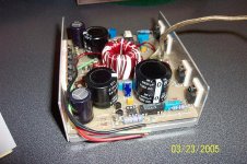
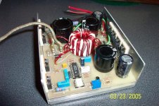
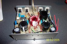
DC-DC SMPS Pics
Here are the pics I promised. The controller is an old Motorola SG3525AN, the MOSFETS are IR IRF540s, and the output rectifiers are MBR10100s (Schottky 10A, 100V) diodes. The optoisolator os an old Motorola MCT271, with a current transfer ratio of 71-117%, giving pretty good regulation. There are no output chokes, but there are traced in the board to put them in, abd eventually, I plan on doing so.
The transformer core called for was originally a pot core from Ferroxcube, 3622, I think, #77 material (u=2000). The core (or cores, I should say) I went with are three stacked FT-114-77 toroids from Amidon Assiociates. These cores can easily handle 150W each at the frequency of 40 kHz, and stacked, they are good for 450W. This is at B(max). The cores begin to saturate at about 200W (each) at 40kHz, so, I'm comfortably within my safety margins. The outputs are (+/-) 33V for the Amp's output sections, and (+/-42V) for the front ends. This was made for an all-MOSFET amp that appeared in a two-part article in 1989-1990 Audio Amateur magazine.
Attachments
- Status
- This old topic is closed. If you want to reopen this topic, contact a moderator using the "Report Post" button.
- Home
- Amplifiers
- Chip Amps
- SMPS for gainclone