No free lunch: with AC bias is modulated by it...
Here's a good discussion: On Correlation Between Residual DHT Filament Hum and AC Frequency. Distortion-induced hum in directly-heated triodes.
It seems the optimum solution would be filaments operating at tiny voltage and huge current. Not likely to happen!
Thanks, as always,
Chris
Look at IR2153, its extremely simple to make a SMPS with it.
I made one +-50V and works good.
You cant feedback the voltage with it but you can make something that is half a feedback: supply an optocoupler with a zener diode and tie its transistor to short the 3rd pin of the IC. The working depends on the optocoupler and I tricked it with a small 2N7000 mosfet between the coupler and the 3rd pin. It worked without the mosfet too but it was audible.
This is "oscillating" feedback which shutdowns the IC when the desired voltage is outed. Then the load drops it and the IC starts again.
Easily, you can make protection too:
diysmps
Look at mine idea at the last page and the last post. Im "expressel" there.
page41
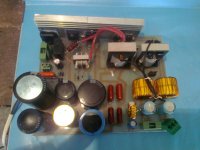
Another SMPS possibility is the 1st attachment (700W) which is self-oscillating design with only 2 power transistors and no IC.
its mosfet version and I got it from post at page #6 where have schematic too.
diysmps)
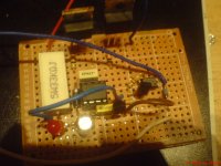
The 2nd is my first one.
I made one +-50V and works good.
You cant feedback the voltage with it but you can make something that is half a feedback: supply an optocoupler with a zener diode and tie its transistor to short the 3rd pin of the IC. The working depends on the optocoupler and I tricked it with a small 2N7000 mosfet between the coupler and the 3rd pin. It worked without the mosfet too but it was audible.
This is "oscillating" feedback which shutdowns the IC when the desired voltage is outed. Then the load drops it and the IC starts again.
Easily, you can make protection too:
diysmps
Look at mine idea at the last page and the last post. Im "expressel" there.
page41
Another SMPS possibility is the 1st attachment (700W) which is self-oscillating design with only 2 power transistors and no IC.
its mosfet version and I got it from post at page #6 where have schematic too.
diysmps)
The 2nd is my first one.
Attachments
Last edited:
Hmm, remembered i have a 22A 5v open frame SMPS i pulled out of a 48-port switch years ago.
It indeed has an adjustment trimpot. With a dab of fingernail polish on it, but that scraped off easily enough.
If i can tweak this up close enough to 6.3v it might work for the 100w amp i am inching toward building.
It indeed has an adjustment trimpot. With a dab of fingernail polish on it, but that scraped off easily enough.
If i can tweak this up close enough to 6.3v it might work for the 100w amp i am inching toward building.
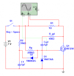
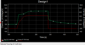
In the above, Cgd' and Rg "help" set the charging rate of MOSFET Q1. Cgd' is in parallel with Cgd of Q1 (MSIM doesn't allow delimiters in component labels.) The red line which shows current through R1 isnt showing negative amps, it was adjusted downward for purposes of clarity.
Obviously, you'd use a low Rds_on MOSFET, and it would need to be heat-sinked.
The active inrush limiter has the advantage of very low power dissipation and quick turn-off.
An Amphenol NTC Inrush Limiter would also work well, but you have to size the device to the application -- they can only dissipate a certain amount of power before they burn up. As they are negative tempco an oversized limiter will dissipate quite a bit of heat.
An interesting application note in the ham radio mag QST May 2017 -- LT4365 is an over-voltage protection IC which can be employed soft start, current limit etc. There's development board from Linear Tech http://cds.linear.com/docs/en/datasheet/4365fa.pdf http://cds.linear.com/docs/en/demo-board-manual/dc1555cfd.pdf
SMPS itself has an IC that also has a control pin, and most of them have current sensor that works through the same opto-coupler as a voltage feedback. Even if it does not, you can always add a resistor in series with load that controls a transistor loaded on the LED in the opto-coupler used to control output voltage.
Just been considering SMPS for a OTL headphone amp driving down to 32-50ohm (yes I am feeling the folly of it), 6.3V and a total of about 20A of filament current but I have a couple of questions given my current setup (I'm still designing/tweaking in spice), voltages at the anode/cathode:
Input 6SN7, 153V
Cathodyne splitter 6SN7, 239V / 100V
Drivers 6SN7 both running at 152V
Output 4x 6AS7 PP (still needs work and I'm considering a tube cad style 'Brazilian' sold-state addition here) 140V anode upper / 100V cathode lower
Firstly keeping the filament-cathode difference voltage below the recommended level:
Heater-Cathode max voltage difference of the 6SN7 is 100V DC with 200V DC+AC peak so how do you keep a SMPS DC referenced to a B+/B- rail?
Then the follow on - with a cathode attached OTL load, how do you keep the SMPS referenced to an AC signal with larger peak swings?
I've also seen a couple of points around filament - that include keeping the filament linked to the audio ground to prevent noise. Is this required if you put some filtering between the SMPS and the filaments?
The B+/B- torriodal would share the same AC cable socket as the SMPS but I could have it's own AC filtering to prevent switching noise going back.
Just seems a bit nuts to try to deliver 126W of constant DC filament power via a torroidal. For the record I would use a commercial SMPS such as a Meanwell rather than DIY the SMPS.
Last edited:
4 6AS7 PP for headphones is just insane IMHO.
I use one 6N1P and one 6N6P per channel in my HP amp and it drives down to 32R.
I used one 6AS7 per channel in PSE for 16R in a previous build.
As far as heater reference, I've never bothered and never had an issue YMMV. If the SMPS is isolated, you reference it the same way as you'd reference a linear supply.
I always use 12V SMPS and run pairs of tubes in series. Much easier to find an off the shelf supply for that. My main rig is using an ATX supply for heaters and B+ via DC boost converters.
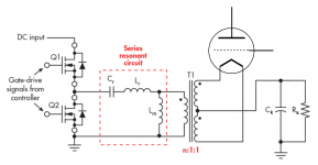
LLC converter
I was also thinking about SMPS heating. There is this possibility to use high frequency and minimize inductances and other parasitic phenomena of the transformer. So, higher frequency leads to smaller inductance and generally smaller size. But then high frequency emissions may increase and become problematic. Unless the SMPS is one of a resonant topology that emits less harmonics. So, I guess a LLC resonant converter would be fine.
The two secondary windings could be bifilar to make them exactly identical. There could be also a fourth winding for voltage measurement and feedback to the controller. The transformer could be a special LLC transformer to decrease number of components.
One possible way to achieve low emissions would be a two stage SMPS. The first stage would be a simple buck converter to adjust the supply voltage of the second stage. The second stage would be a LLC converter that would do exact zero-point switching all the time. It would self-resonate, and the current waveform would look smooth. Measured output voltage would be used as a feedback for the buck converter.
Attachments
run it through a 2 -5 uH air core inductor then into 4700 uf / 16 volt cap.
A lot of SMPS would complain at you putting 4700uf on the output.
Also, the heaters are very low impedance when cold.
A recipe for disaster unless you use a very well spec'ed SMPS to allow.
I tried a 20 watt SMPS on a hybrid amp and the amp just sat there and clicked in time with power rails going on and off !
Use a cheap one with no overload protection or a SMPS many times larger than you need. AKA for 5A use a 20A supply.
This one will light up 4 6P43P and 2 6F12P (pairs in series) along with a DC boost converter. It has to try into the load twice, but then it will latch.
AC-DC 110V 220V 230V to 12V 6-8A 100W Converter Switching Power Supply Module | eBay
This one is good for a pair of 6F12P in series.
12V 500mA AC-DC Power Supply Converter Step Down Module Electronic Transformer | eBay
4 6AS7 PP for headphones is just insane IMHO.
I use one 6N1P and one 6N6P per channel in my HP amp and it drives down to 32R.
I used one 6AS7 per channel in PSE for 16R in a previous build.
As far as heater reference, I've never bothered and never had an issue YMMV. If the SMPS is isolated, you reference it the same way as you'd reference a linear supply.
I always use 12V SMPS and run pairs of tubes in series. Much easier to find an off the shelf supply for that. My main rig is using an ATX supply for heaters and B+ via DC boost converters.
Two 6AS7s (4 triodes I should have said) - my second tube would be an option that could be added in at a later date. Idea being a his and hers as an option.
Last edited:
Intermodulation products and SMPS
If the heater frequency is 60 kHz or more then intermodulation products caused by the heater SMPS should not become problematic.
Calculate intermodulation products from 2 and 3 frequencies.
I was also thinking about SMPS heating. There is this possibility to use high frequency and minimize inductances and other parasitic phenomena of the transformer. So, higher frequency leads to smaller inductance and generally smaller size. But then high frequency emissions may increase and become problematic. Unless the SMPS is one of a resonant topology that emits less harmonics. So, I guess a LLC resonant converter would be fine.
If the heater frequency is 60 kHz or more then intermodulation products caused by the heater SMPS should not become problematic.
Calculate intermodulation products from 2 and 3 frequencies.
Why does everyone still have the impression that switching supplies spew RF hash? Most are really quiet. This isn't the 1980s anymore where they would go unstable without a load.
If you can't adjust a supply up high enough take a look at the circuit that the pot is part of. Chances are it's just a fine adjustment of an already set ratio. Change the ratio a bit and you're good. Just remember to keep an eye on the wattage.
If you can't adjust a supply up high enough take a look at the circuit that the pot is part of. Chances are it's just a fine adjustment of an already set ratio. Change the ratio a bit and you're good. Just remember to keep an eye on the wattage.
TME carries cores that would be suitable for a DIY SMPS to feed valve heaters.
I agree most SMPS nowadays are quiet enough to be used in tube amplifiers. Provided you get a quality one
I agree most SMPS nowadays are quiet enough to be used in tube amplifiers. Provided you get a quality one
Hi everybody!
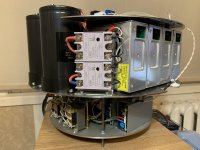
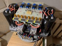
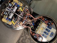
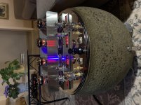
I finished lately my "Tim Mellow Project" with little changes from original.
Biggest difference is power supply which is made on 6 SMPS. Four of them are working for +/- 150V rail (L&R channels separated), one is providing 6,3V for pre and driver stages and one is just for 24V supportive source (timers + fans).
Result: the amp is dead quiet and the dynamics feels endless...
I named it Rolling Stone - couple of pics as well...
Attachments


- Home
- Amplifiers
- Tubes / Valves
- SMPS for filament heating of power triodes?