Slash: if you've got noises (usually audible), then you obviously didn't connect frequency compensation (at pin9).
It's better to show then verbally explain: here are pictures of one of my old schematics, tried a lot of times, working well. C101 is for compensation - you can try lower value for better transient response. I usually left R207 open in PCBs.
It's better to show then verbally explain: here are pictures of one of my old schematics, tried a lot of times, working well. C101 is for compensation - you can try lower value for better transient response. I usually left R207 open in PCBs.
Attachments
Slash: This is secondary part of converter. As you see, feedback is made the primitive way, yet it's sufficient for the most power amps. I wonder that you say about output inductor as a "requirement": using secondary inductor in such regulated PWM converter is a rule of good form.
Certainly you can find some cheap commercial converters that claim regulation omitting inductor. In this case regulation function is performed mainly by primary stray inductance of transformer. This mode is potentially dangerous for FETs - at the point of regulation they work at very short drive pulses and high peak currents. It is used only in low-power circuits like up to 200-300W.
Certainly you can find some cheap commercial converters that claim regulation omitting inductor. In this case regulation function is performed mainly by primary stray inductance of transformer. This mode is potentially dangerous for FETs - at the point of regulation they work at very short drive pulses and high peak currents. It is used only in low-power circuits like up to 200-300W.
Attachments
Disney_SK:
my saying "I don't know about Tripath" was only about practical measurements of output power vs. DC rails of real application of so called class-T amplifier. I really didn't measure TA3020 performance yet, but I have such possibility and plan to do it soon.
These are claims for TA3020 output power at 4 ohm load, taken from Tripath' website. The rightmost column is my own calculation of supply usage ratio (RSU) for equivalent output power pure sinewave. Supply usage is ratio of maximum amplitude at specified THD level to DC rail.
2 x 300W +/-45.0V 10.00% THD 108,8% RSU
2 x 220W +/-45.0V 1.00% THD 93,2% RSU
2 x 150W +/-45.0V 0.03% THD 77,0% RSU
So the question in only about acceptable level of THD that can be still considered a music signal (why, output square wave has some higher THD but provides impressive 2 times more output power then the sinewave of same magnitude 😀 ).
When I was talking about supply rails maximum usage by other D-class amplifiers, I took the point of "maximum power" at THD level of about 0,1-0,2% which is usually considered to be acceptable when listening to music.
Looks like my pointed 80-85% RSU for other switching amplifiers are close to those of Tripath' chips at similar distortion levels.
Anyway I'm interested in your report about amplifier performance after you accomplish and test it.
Alme,
Thank you for the schematics a lot. I will check them a couple of days later. But I have one more question: What should I see on my oscilloscope using this schematisc?
And guys, is it necessary to make regulated power supply for 1KW amp and if not, will it affect the dynamics of sound at full power?
Slash: of course you should see two clean out-of-phase square signals with minimum overshoot at the gate drive outputs of SG3525, varying in width as you change primary DC voltage (this is under steady load; under real amp load they will also change dynamically mostly in time of low-frequency signals at amp output).
There is no usual need to make regulated supply even for 1kW amplifier. Sometimes they put regulation for the purpose of limiting secondary rails in the case of too high input DC voltages.
I don't know exactly what you mean under "sound dynamics"; if it's about maximum peak power for low-frequency signals - yes, rail voltages drop quite significantly being connected to low speaker impedance during bass peaks; the only help here is to increase secondary rails capacitors.
I think 20,000uF per each rail is some minimum for such high output power as 1kW.
Alme, can you please explain, why people want to avoid regulation in SMPS for amp-supplying purposes?
Because I think regulation is very simple if you already have a PWM controller, that you need for operation of even non-regulated SMPS. I do not know the reason not to implement regulation in those supplies.
Because I think regulation is very simple if you already have a PWM controller, that you need for operation of even non-regulated SMPS. I do not know the reason not to implement regulation in those supplies.
4 slash:
If you made a standard class AB amplifier, there is usually no relation between supply rail voltage and GAIN, there is only relation between supply rail voltage and maximum output POWER.
So, if the rail voltage will drop at full power, it will not affect the dynamics of the signal, but it will affect maximum output power and distortion.
But if you would made a class T amplifier, there IS relationship between supply voltage and GAIN (I found out that 1V supply drop causes about 1dB gain drop). Of course, in class T the rails voltage will also affect maximum output power.
Disney_SK: explaining why they omit regulation in certain circuits.
Because regulation is first of all adding bulky output inductor, which is increasing cost, PCB space, and decreasing converter efficiency (and thus overall system efficiency) for the same other conditions.
If you don't definitely need stabilized rails as is the need in some cases, then why go for more cost and complexity? Just make it cheap and simple 🙂
>Just make it cheap and simple 🙂
Yes, in regulated SMPS I need bulky output inductor, but I do not need bulky output capacitor. Look at the capacitance - for example in PC power supply... 1mF for 30A output. And If these capacitors have capacitance at least 10 times higher than calculated minimal capacitance (in my case about 80uF) and you have properly calculated inductance, output noise and voltage stability is given only by the ESR of these capacitors...
Decreacing efficiency? Do you mean losses in inductor core and wiring? Well, my inductors have 6W core losses and 5W wiring losses at full power 😀
Alme said:Disney_SK: explaining why they omit regulation in certain circuits.
Because regulation is first of all adding bulky output inductor, which is increasing cost, PCB space, and decreasing converter efficiency (and thus overall system efficiency) for the same other conditions.
If you don't definitely need stabilized rails as is the need in some cases, then why go for more cost and complexity? Just make it cheap and simple 🙂
add to this the fact that regulation, by definition, adds feedback loop (error amplifier to pass transistor for linear supplies, error amplifier to duty cycle for switching supplies) so you have to compensate the feedback loop so that it is stable at the unity gain frequency...not rocket science but not simple either.
choose an amplifier design with good power supply rejection figures, then you can go with an unregulated design.
Disney_SK: man, you seem to know everything, at least in theory 🙂
Maybe I should not build lots of amplifiers and power supplies before saying like this?
>> for example in PC power supply... 1mF for 30A output
First, computer current consumption is rather steady comparing to amplifier consumption.
There are the filter caps that deal effectively with large current transients.
Second, computer supplies last years are made completely by Chinese - do you know what it means? - that all components are diminished to ridiculous values. Compare their design with decent PC supplies made in about 1991, or bigger and reliable server supplies and feel the difference.
>> And If these capacitors have capacitance at least 10 times higher than calculated minimal capacitance (in my case about 80uF) and you have properly calculated inductance, output noise and voltage stability is given only by the ESR of these capacitors...
Everything may look nice in theory. To sustain output voltage effectively during high-power low-frequency current peaks, large capacitors are very desirable, if not inevitable: they can store energy peaks and make current consumption more steady. Output noise in reality depends much on your choke and transformer (yes, transformer) design, not on LC product. Guess why.
>> Well, my inductors have 6W core losses and 5W wiring losses at full power
When I say about efficiency, this means overall efficiency. Do you think that adding some serial element will decrease efficiency by only its own dissipation?
I propose you just to make measurements with some power supply and amplifier, including and excluding secondary choke and comparing results.
After this, we can return to the topic to explain the effect.
Dell's server supplies for the Chinese market are made in China, but those for the U.S. and ROW are made in Thailand -- at least as far as I can tell with the servers that I have taken apart (and they are a pia to unsolder, but the components are first rate.)
Michael Dell made this point when being interviewed on CNBC about a year ago.
Michael Dell made this point when being interviewed on CNBC about a year ago.
For continuous conduction mode, the inductor value together with the operating frequency determine the current ripple across the inductor. I like ripple values around 10% but this simetimes requires too much inductance
Required output capacitor value depends on inductor value, inductor ESR and capacitor ESR. The optimum capacitance together with the inductance and both ESRs should form a 2nd order filter with no overshoot. Reducing capacitor value produces overshoot and reduces phase margin requiring heavier frequency compensation and degrading transient response
Output capacitor value is not related to output current capability at all
Have you performed any transient response tests on your SMPS? This is also essential to optimize the frequency compensation of the regulation loop before attempting to power any amplifier with it.
BTW, which type of amplifier topology is usually used to compensate the feedback loop (type 1,2 or 3 amplifier?), I have used the type 2 amplifier (zero-pole pair) to compensate with good results, but in some books the type 3 amplifier (two-pole two zero) is recommended for push-pull, half-bridge and full bridge topologies, and even is some amplifiers I have seen type 1 amplifier (single-pole) implemented, so which one is usually used?
The optimum capacitance together with the inductance and both ESRs should form a 2nd order filter with no overshoot
Simulating in workbench I can see that a capacitor with relatively large ESR (around 0.1 ohm) or a large winding inductor resistance, or even a combination of both, solves the overshoot problem, is this the way to do it?, I mean, we need to get a capacitor/inductor with those characteristics?. For example, if our capacitor has a small ESR (>0.01 ohm) that will produce an overshoot, one solution could be put an 0.1 ohm resitor in series with the cap to suppress the overshoot, is this ok?
J.Carlos said:
BTW, which type of amplifier topology is usually used to compensate the feedback loop (type 1,2 or 3 amplifier?), I have used the type 2 amplifier (zero-pole pair) to compensate with good results, but in some books the type 3 amplifier (two-pole two zero) is recommended for push-pull, half-bridge and full bridge topologies, and even is some amplifiers I have seen type 1 amplifier (single-pole) implemented, so which one is usually used?
J.Carlos said:
Simulating in workbench I can see that a capacitor with relatively large ESR (around 0.1 ohm) or a large winding inductor resistance, or even a combination of both, solves the overshoot problem, is this the way to do it?, I mean, we need to get a capacitor/inductor with those characteristics?. For example, if our capacitor has a small ESR (>0.01 ohm) that will produce an overshoot, one solution could be put an 0.1 ohm resitor in series with the cap to suppress the overshoot, is this ok?
Yes, this is how I do it. Increasing Rdc of the inductor damps the filter but inductor I^2*R losses put a practical limit on Rdc. Incresing capacitor ESR also damps the filter but at the expense of increased output ripple and capacitor losses. A compromise between size, ripple and losses has to be found
To compensate buck regulators with voltage mode control the usual approach is a pole in the origin plus a zero near the poles of the output filter
In average current mode buck regulators there are a current amplifier and a voltage amplifier. For the current loop I've succesfully used a pole at the origin plus a zero at 1/10 of the switching frequency and an additional pole above Fsw. For the voltage amplifier a single pole appears to work fine
In average current mode buck regulators there are a current amplifier and a voltage amplifier. For the current loop I've succesfully used a pole at the origin plus a zero at 1/10 of the switching frequency and an additional pole above Fsw. For the voltage amplifier a single pole appears to work fine
Alme said:
Everything may look nice in theory. To sustain output voltage effectively during high-power low-frequency current peaks, large capacitors are very desirable, if not inevitable: they can store energy peaks and make current consumption more steady. Output noise in reality depends much on your choke and transformer (yes, transformer) design, not on LC product. Guess why.
I have 4mF capacitance at input, 3mF/rail capacitance output with 100uF inductors in series. You can easily calculate, how much energy can 4mF caps charged at 385V deliver to the supply. When I have good feedback loop, which can handle high-current peaks to keep the output voltage within 59.5 - 60.5 V (including overshoot) at full-power DC peak, I think there is no reason to put additional bulky capacitance on output.
Alme said:
When I say about efficiency, this means overall efficiency. Do you think that adding some serial element will decrease efficiency by only its own dissipation?
I propose you just to make measurements with some power supply and amplifier, including and excluding secondary choke and comparing results.
After this, we can return to the topic to explain the effect.
I do not have an access to hi-tech lab, so I can only experiment with instruments I got - scope, generator and meters and software. Can you please explain why an inductance should decreace efficiency of the supply in other way than introducing its own serial resistance?
Well, we went far from topic now 🙂
I'll try to explain according to my own experience. Usually when I added secondary inductor into converter output rails (generally coupled for both rails regulation), I had power loss not only in that inductor but also increased loss in switches. I suppose that additional dynamic loss in switches is caused by increased parasitic components when adding inductor, which form high-frequency resonant circuits (rectifier capacitance, transformer stray inductance, inductor capacitance), or inductor makes "decoupling" effect to transformer/rectifier tank circuit; this is not easy matter for me to describe but I've got such a fact. I also noticed that this effect depends a lot on transformer design and converter topology. The worst case is usually a pair of push-pull center tap converter and toroidal transformer (which obviously has high capacitance between windings). This is may be an explanation why power designers don't like to add regulation into such converters. In case if you have half-bridge converter and well-designed EI/ETD transformer, the above effect may be small, I beleive in such converter the most of energy stored in resonant circuits is recuperated back into primary supply thru FET reverse diodes. A lot depends on magnetic coupling and this is again transformer design issue.
Concerning noise; to me switching supply noise consists of two components: ripple and high-frequency noise. Ripple is quite easily predicted and calculated as long as designer knows filter L+C values and capacitor ESR. Actually, in the present time when converters operate at tens or hundreds kilohertz, one may have neglecting ripple value even with modest 100uF capacitor in filter, because frequency squared is a denominator to define ripple after LC-filter 😎
But, high frequency noise, that is a headache: there still is not only capacitors ESR but also ESL, and there are also rectifier+inductor+transformer parasitics... So actually this noise component is much dominant overall when we are talking about hard-switching converters. That's why I said before that magnetic element design is very critical regarding noise. Other widely used solutions to lower switching noise are RC-snubbers parallel to rectifiers, and also second LC-filter with low L value to fight those megahertz noise. These can be found very near, in PC power supplies 🙂
Well, now I see that there is much more to do about RFI and EMI suppression in my design
Actually I noticed that this amp, even in metal case is causing an interference to my second class AB amp and VHF mic receiver. When I put them closer than about 2 meters to the unit, I get silent, but audible hiss from speakers, and I have to set the squelch at the receiver to relatively high value to avoid noise.
I also noticed that noise level is not dependent on actual signal amplitude, it is still constant.
There are only 1uF capacitors at the mains input and after the diode bridge and RC snubbers at the gates of the switching mosfets (1nF and 4k7 in series) connected between source and gate, I did not implement anything other to suppress the high frequency noise. Obvidously, the supply is not interfering with class T amp modules inside the case, only with other devices placed close 🙁
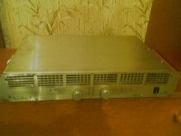
Here I attach a photo of the amp (sorry for the quality, but I do not own better camera). I am still planning to cover these ventilation holes with dense steel wire-net (sorry for my bad english :-( ) to avoid electromagnetic propagation by suppressing its electric part. I can also send you hi-res photos by e-mail from inside the amp and SMPS schematics to check.
Actually I noticed that this amp, even in metal case is causing an interference to my second class AB amp and VHF mic receiver. When I put them closer than about 2 meters to the unit, I get silent, but audible hiss from speakers, and I have to set the squelch at the receiver to relatively high value to avoid noise.
I also noticed that noise level is not dependent on actual signal amplitude, it is still constant.
There are only 1uF capacitors at the mains input and after the diode bridge and RC snubbers at the gates of the switching mosfets (1nF and 4k7 in series) connected between source and gate, I did not implement anything other to suppress the high frequency noise. Obvidously, the supply is not interfering with class T amp modules inside the case, only with other devices placed close 🙁
Here I attach a photo of the amp (sorry for the quality, but I do not own better camera
). I am still planning to cover these ventilation holes with dense steel wire-net (sorry for my bad english :-( ) to avoid electromagnetic propagation by suppressing its electric part. I can also send you hi-res photos by e-mail from inside the amp and SMPS schematics to check.Attachments
blown PC power supplies have wonderful cores for power line chokes/EMI filters --Disney_SK said:Well, now I see that there is much more to do about RFI and EMI suppression in my design
wrt snubbing diodes and switches -- in OnSemi's Diode Encyclopedia there is a very comprehensive discussion, also look to International Rectifier, Fairchild Semiconductor, Texas Inst.
While the efficiency drops very noticeably, the slew-controlled switchers from Linear can be used with a minimum of EMI filtration -- problem is the unit cost -- most folks on DIYAUDIO seem to like the SG3524 or SG3524 or TL494 which can be had for $0.50 or less. A slew control chip costs $6 or more, and is only available in surface mount.
- Status
- Not open for further replies.
- Home
- Amplifiers
- Power Supplies
- SMPS both rails stabilization