a smps is very difficult. and all the diagram which one finds on the forum does not function even any more if they functions it is only for one short period. I devoted more than 4 years for my first
smps functional has long run. there are many secrecy and details that nobody wants to share. to manufacture smps and a very profitable project and also very very difficult. and it is for that nobody
does not want to reveal these important secrecy
smps functional has long run. there are many secrecy and details that nobody wants to share. to manufacture smps and a very profitable project and also very very difficult. and it is for that nobody
does not want to reveal these important secrecy
Attachments
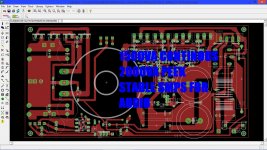
There does not look to be sufficient creepage under that EMC cap below the transformer (Also between the line fuse and the mounting screw?), this is actively dangerous.
Class II at 1,000W+ is also somewhat unusual, most gear up there is class I.
Moving the EMC cap up to the top of the board and bringing the resulting non isolated side down between the two HV terminals of the transformer would make opening up that clearance easier and you could have a milled slot to increase the creepage.
From the look of things this is a two switch hard switched half bridge with no feedback, and no current limiting, 1985 called and wants its switcher back.
Also, I am a little suspicious about the things EMC performance, there are some fairly large loops on that layout.
Finally, only one cap per rail at possibly ten AMPS or so of ripple? Seems possibly a little optimistic.
I don't know where these deep secrets in switcher design are supposed to hide, there are plenty of books on the subject, and some of the app notes are quite good as well.
Regards, Dan.
I have designed a few SMPS of various types.
I prefer LLC SMPS. On mine I used a PIC micro to supply the frequencies and IR2113 to supply gate signals to two mosfets. I use an opto for feedback to regulate the output voltage.
LLC applies a sine wave to the transformer so noise is less of a problem.
I found the transformer to be the hardest part. I built one and then worked out leakage and main inductance. From this I could work out the two frequencies the PIC needed to supply for on and off load.
hello and thank you for your comments. this smps is carried out to be the least expensive that possible. and to function with a great power long run has. it is a smps for audio amplifier preferably class D, therefore not need to be controlled. the input capacitance is of 2*470 uf 450v in the rail 320v. the electronic board is made to have smallest dimension. and yes there is full with secrecy yes full. to be effective during one long period. this map east tests and goes from there without any problem in an audio amplifier classifies D 2*1kw 1u. on this design I took the account height 4.4 cm to be included in an amplifier 1u. yes it is hardware switching and I too am telling. thank you for your comments.
- Status
- Not open for further replies.