Wondering what ideas people have for reducing a voltage spike at turn-on. I have a 1n4007 full-wave bridge into CLC (first small C .2uf) filter. 350v transformer and 15H choke, about 30mA load. I have a spike up to over 540v before it settles to about 320v. How can I eliminate, or at least greatly reduce this spike. I've gone through 2 SSHV regs before I went back to this PS design and realized that this spike is killing the reg. D: I know.. idiot right!? I guess one solution could be a TV damper diode, but what other alternatives are there?
-MW
-MW
Actually I have an answer to my own q. If a resistor is placed in series with the choke, then the spike can be sufficiently damped. The spike is due to an LC resonance and not a spike from line AC.
-MW
-MW
Maybe a pair of CL-50s on the AC in and a pair on the secondary AC out. They get hot so keep them away from things.....
You can add an "intelligent" clipper: it will not create additional drops or losses, and it can be made cheap and reliable.
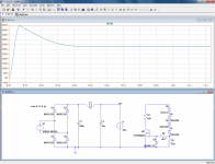
Here is an example.
The first pic is the initial circuit: the peak voltage exceeds 540V before settling to 327V.
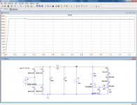
Next is the situation when the clipper is connected: the output is clamped to ~337V (the voltage of the zeners string + Vgth).
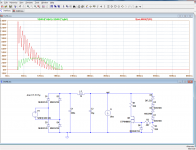
The clever bit is the resistor R1: it bears most of the dissipation, and relieves the MOS. The dissipation in the MOS (green) never exceeds ~35W, and only for a short time, a few tens of ms. This means that you don't need an actual heatsink: just a small block of aluminum, for thermal inertia.
The dissipation in the resistor (red) reaches 135W, but only for a short time.
A 10W resistor would amply suffice for this job.
After a mere 200ms, the show is over, and no additional power is dissipated anywhere
Here is an example.
The first pic is the initial circuit: the peak voltage exceeds 540V before settling to 327V.
Next is the situation when the clipper is connected: the output is clamped to ~337V (the voltage of the zeners string + Vgth).
The clever bit is the resistor R1: it bears most of the dissipation, and relieves the MOS. The dissipation in the MOS (green) never exceeds ~35W, and only for a short time, a few tens of ms. This means that you don't need an actual heatsink: just a small block of aluminum, for thermal inertia.
The dissipation in the resistor (red) reaches 135W, but only for a short time.
A 10W resistor would amply suffice for this job.
After a mere 200ms, the show is over, and no additional power is dissipated anywhere
Attachments
- Status
- Not open for further replies.