jleaman said:
Well i do have all the same parts as russ and brian are using, I even went over each resistor and checked.
The QX?, CCS FET, has a threshold with a wide spec. It's actuall threshold, the value of the zener at the gate and the 27 ohm resistor determine your differential pair's current. Your FET could be slightly lower Vgsth causing slightly higher current in your circuit. If so, this could be adjusted with a slightly larger source resistor.


At least one of the schematics in this thread, although I can't see it very well, calls the CCS FET QX. I don't know??? I'm just trying to help...
http://www.diyaudio.com/forums/attachment.php?s=&postid=713646&stamp=1125427483
and
http://www.diyaudio.com/forums/attachment.php?s=&postid=765413&stamp=1131830767
Sometimes I actually do
http://www.diyaudio.com/forums/attachment.php?s=&postid=713646&stamp=1125427483
and
http://www.diyaudio.com/forums/attachment.php?s=&postid=765413&stamp=1131830767
Sometimes I actually do
Banned
Joined 2002
jleaman said:ok so i got it powered up now after waiting a whyle plus getting the parts. The new resistors are in and elevated and still getting warm, when i check R2 R7 and so on the voltages start at 37V and count down.
On both Channels.
What should i look and measure now.?
give us schematic here ;
this thread is nothing else than walking in cloud if we are without reference.
you want that someone help you?
than do your homework
Banned
Joined 2002
Zen Mod said:
give us schematic here ;
this thread is nothing else than walking in cloud if we are without reference.
you want that someone help you?
than do your homework
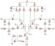
I can try, im not sure what schematic was used i did find this one that some one has helped me with. It didn't come with a schematic, it just comes with a parts list and the values and you plug them in and it is suppose to work.
Here is a shot tho,
I appreciate your help.
Attachments
jleaman said:
I can try, im not sure what schematic was used i did find this one that some one has helped me with. It didn't come with a schematic, it just comes with a parts list and the values and you plug them in and it is suppose to work.
Here is a shot tho,
I appreciate your help.
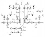
well - if you didn't already - you must increase negative supply to at least minus 15 V , to be sure that CCS is working with enough margin ;
next :
look at values of DC voltages at schematic , and try to measure what you have in circuit , then write exactly where you measure different voltages ;
all voltages are calculated and wroted as they are measured from gnd level .
be sure that any resistor's body (even smallest one ) isn't in contact with upper traces - if your pcbs have any ; I can't see pics of your pcbs, they are vanished
Attachments
Banned
Joined 2002
Banned
Joined 2002
anatech said:Hi Jason,
Does that mean there is no current flow possibly?
Check that your current source is operating.
-Chris
And what should i measure ?
Hi Jason,
Something. I don't know because I have not built one of these as yet. I may in the future some time.
If you look at the schematic posted by Choky, it indicates a drop around 1 VDC. Looking at the 100 mA current source, one would expect 50 mA down that leg. From that information you ought to be able to calculate all your voltage drops.
Since you have nothing, how about the other side? Is the voltage drop also zero (sorry, coming in late)? If not, then I suspect it is double what it should be. So if that is drawing all the available current, you may find something seriously amiss there.
If no current is flowing on the other side, then your current source is not working. Fix it.
-Chris
Banned
Joined 2002
I hope that i too am helping you help me, i am not trying to follow instruction,
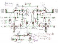
ok so on this schematic it says to check R8 on his schematic he said i should be getting about 2.15V im getting 2.5 V
I should mention that i am listening to this pre-amp right now, i am monitoring the heat off of the 3 watt resistors.
ok so on this schematic it says to check R8 on his schematic he said i should be getting about 2.15V im getting 2.5 V
I should mention that i am listening to this pre-amp right now, i am monitoring the heat off of the 3 watt resistors.
Attachments
Hi Jason,
It appears as though R1 and R6 may be open if you have 60 some odd volts across them. Shut it down and measure the resistances. Then recheck all solder connections and watch out for shorts. If you haven't done so, remove all the flux before going any further and examine your PCB.
Are you using a board from Choky?
-Chris
Alright, I'm no expert, but this might be within normal bounds. If you were to replace the IRF610 (QX), your voltage drop would probably change also. Therefore, your current source appears to be working at the very least. The current is a little off.ok so on this schematic it says to check R8 on his schematic he said i should be getting about 2.15V im getting 2.5 V
It appears as though R1 and R6 may be open if you have 60 some odd volts across them. Shut it down and measure the resistances. Then recheck all solder connections and watch out for shorts. If you haven't done so, remove all the flux before going any further and examine your PCB.
Are you using a board from Choky?
-Chris
Banned
Joined 2002
Banned
Joined 2002
anatech said:Hi Jason,
Alright, I'm no expert, but this might be within normal bounds. If you were to replace the IRF610 (QX), your voltage drop would probably change also. Therefore, your current source appears to be working at the very least. The current is a little off.
It appears as though R1 and R6 may be open if you have 60 some odd volts across them. Shut it down and measure the resistances. Then recheck all solder connections and watch out for shorts. If you haven't done so, remove all the flux before going any further and examine your PCB.
Are you using a board from Choky?
-Chris
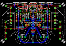
No im using this board, i have checked all resistors, i have checked all soldering joints. If it burns up, im tossing it in the garbage way to much time wasted into this project.
I might as the original designer that lives in Vancouver if he would mind looking at it if i sent it to him.
Jase
What is weird tho also is that this thing is playing very clean and very good sound, i'm happy, no hums either, just the minor problem of the resistors getting warm.
Attachments
jleaman said:I hope that i too am helping you help me, i am not trying to follow instruction,
ok so on this schematic it says to check R8 on his schematic he said i should be getting about 2.15V im getting 2.5 V
I should mention that i am listening to this pre-amp right now, i am monitoring the heat off of the 3 watt resistors.
jleaman said:
No im using this board, i have checked all resistors, i have checked all soldering joints. If it burns up, im tossing it in the garbage way to much time wasted into this project.
I might as the original designer that lives in Vancouver if he would mind looking at it if i sent it to him.
Jase
What is weird tho also is that this thing is playing very clean and very good sound, i'm happy, no hums either, just the minor problem of the resistors getting warm.
How hot do the resistors get now? Smoking or just not nice to touch?
Magura
Banned
Joined 2002
Magura said:
How hot do the resistors get now? Smoking or just not nice to touch?
Magura
Well they are not smoking hot, but i can leave my finger on there for about 1 second,
p.s thanks for jumping in and also helping.
Jase
Banned
Joined 2002
mpmarino said:How long can you hold your tongue there?

Seriously, If your talking about the power resistors - they get pretty hot normally. Not smoking, but pretty hot.
I tried to put my tongue on there but it curled up and went back inside, i think it is scared
mpmarino said:
Seriously, If your talking about the power resistors - they get pretty hot normally. Not smoking, but pretty hot.
Exactly my thought....your circuit is fine.
Magura
- Status
- This old topic is closed. If you want to reopen this topic, contact a moderator using the "Report Post" button.
- Home
- Amplifiers
- Pass Labs
- Smoking HOT X-BoSoZ HELP!