When the day has 48 hours and I have no day job, maybe I can find the time to create that kit you talk about and maybe even earn some money selling it.... for now there is no kit just a board with enough options to make most people happy.... or so I hope.
I don't belive in kits for this sort of project, everyone has favorite parts that they want to use, so there would be a need for 3 or more kits so satisfy everyone... I honestly have better things to do than putting components in bags right now.
\Jens
I don't belive in kits for this sort of project, everyone has favorite parts that they want to use, so there would be a need for 3 or more kits so satisfy everyone... I honestly have better things to do than putting components in bags right now.
\Jens
JensRasmussen said:just a board with enough options
Jens,
not just a board, a very nice one, 2 very nice ones actually.
You must be one of those with a girlfriend, a job, a house, and a life ?
Mmm, interesting.
It wasn't reproach to you, Jens... 😉 From my side it was only suggestion for more detailed building informations, such as basic wiring diagram and it is, by my opinion, any problem....
Dave S said:Hi Terry,
Here is my concern:
When you connect a signal source you will get a ground loop I.e. L source -> L input -> L power star on pcb -> Main power star -> R power star no pcb -> R input -> R source. This loop area could be subject to induced current by the mains transformer and could also be prone to high frequency interference. You could also have a conflict because the pcbs appear to have a power ground (by virtue of the large rail caps on board) as well as the busbar on your main smoothing caps. Please also do not believe that a separate bridge rect for each channel gives you some sort of isolation - when the diodes are conducting the L+R power rails are connected to each other through a low impedance.
Because Jens has put the large electrolytics on the pcbs (and therefore a power star) you don’t really have the option to build a stereo amp with just one supply - and critically one power ground. Therefore I think you need to go dual mono.
If you look at Prof L’s layout he is fully aware of these issues and he places the L+R inputs physically close to avoid large loop areas. He also has just one power ground star.
If I could make a suggestion - it may be best to remove the busbar and associated caps, and fit another mains transformer in the vacated space. Then build a dual mono using the pcb power ground as speaker return etc.
Hi Dave,
I can't find it right now but I addressed the grounding issue already. I solved the loop by connecting the PCB grounds through the input grounds. I followed directions from Dr Leach. I have no hum in this amplifier. The two bridge idea was just something I wanted to try. It works fine AFAIKT. I also used a regulator for the front end. Something else I wanted to try. This is all a learning experience for me. I'm not necessarily looking to build the best audio amplifier as much as I am trying to learn something with each amp I build. I don't have time to take any courses in electronics, so I am doing this instead. I'm sure that this amp would have worked better built as dual mono but I had this transformer and wanted to see how well it would work. It is working surprizingly well IMO. I doubt I will do any more to this amp. I had another pair of these PCB's but gave them to a friend who wants to try his hand at DIY audio. Maybe I'll talk him into trying dual mono. 😀
I'm not sure I understand why having large smoothing caps on the PCB causes the problems you are stating. Maybe Jens can comment on it.
Blessings, Terry
Caps
Hi Terry,
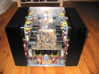
I have a central cap bank in my current Leach amp (PIC), it has 24 x 10000µF in it.
On the amp boards I have 2 x 10000µF.
The main charging currents for the caps are running through short wires generating small loops and therefor emitting only little noise.
The caps on the amp boards are intended as speed caps, and can be anything between 1000uF and 10000uF depending on use of the amp.
On my next system:
I will use 10000µF on my sub amps and 1800µ on the other channels.
I will use a central cap bank of +300000µF for an eight channel setup.
I hope this helps you.
now back to soldering 🙂
\Jens
Hi Terry,
I have a central cap bank in my current Leach amp (PIC), it has 24 x 10000µF in it.
On the amp boards I have 2 x 10000µF.
The main charging currents for the caps are running through short wires generating small loops and therefor emitting only little noise.
The caps on the amp boards are intended as speed caps, and can be anything between 1000uF and 10000uF depending on use of the amp.
On my next system:
I will use 10000µF on my sub amps and 1800µ on the other channels.
I will use a central cap bank of +300000µF for an eight channel setup.
I hope this helps you.
now back to soldering 🙂
\Jens
Attachments
Re: Caps
Hi Jens,
Wow!😱 That's a lot of filter. Do you think this amp design requires that much? All I used was a pair of 28000uf per channel and 2x15,000uf caps on the board. I see you are recommending 1,00uf to 10,000 on the boards. Do you think I will have trouble with the 15,000uf caps?
By the way, is that a four channel amp in the pic?
What I didn't understand from Dave is what he means when he says
How do the caps on the board create a power star? I thought the large electro's on the board were for smoothing. I think you just said they were for speed. Do the cause extra star grounds?
Thanks, Terry
JensRasmussen said:Hi Terry,
I have a central cap bank in my current Leach amp (PIC), it has 24 x 10000µF in it.
On the amp boards I have 2 x 10000µF.
The main charging currents for the caps are running through short wires generating small loops and therefor emitting only little noise.
The caps on the amp boards are intended as speed caps, and can be anything between 1000uF and 10000uF depending on use of the amp.
On my next system:
I will use 10000µF on my sub amps and 1800µ on the other channels.
I will use a central cap bank of +300000µF for an eight channel setup.
I hope this helps you.
now back to soldering 🙂
\Jens
Hi Jens,
Wow!😱 That's a lot of filter. Do you think this amp design requires that much? All I used was a pair of 28000uf per channel and 2x15,000uf caps on the board. I see you are recommending 1,00uf to 10,000 on the boards. Do you think I will have trouble with the 15,000uf caps?
By the way, is that a four channel amp in the pic?
What I didn't understand from Dave is what he means when he says
Because Jens has put the large electrolytics on the pcbs (and therefore a power star) you don’t really have the option to build a stereo amp with just one supply - and critically one power ground. Therefore I think you need to go dual mono
How do the caps on the board create a power star? I thought the large electro's on the board were for smoothing. I think you just said they were for speed. Do the cause extra star grounds?
Thanks, Terry
djk said:and I intend to try the Threshold output stage with the Electrocompaniet front-end regulator.
DJK,
output stage as in ? Stasis ?
And the regulator of which of Per Abrahamsen's designs ?
Re: Caps
In my experience you will get better sound with 2 X 10KuF on the pcb, no central bank of capacitors and separate windings for each channel.
You are all at liberty to ignore my experience for whatever reason you may choose.
JensRasmussen said:Hi Terry,
I have a central cap bank in my current Leach amp (PIC), it has 24 x 10000µF in it.
On the amp boards I have 2 x 10000µF.
The main charging currents for the caps are running through short wires generating small loops and therefor emitting only little noise.
The caps on the amp boards are intended as speed caps, and can be anything between 1000uF and 10000uF depending on use of the amp.
On my next system:
I will use 10000µF on my sub amps and 1800µ on the other channels.
I will use a central cap bank of +300000µF for an eight channel setup.
I hope this helps you.
now back to soldering 🙂
\Jens
In my experience you will get better sound with 2 X 10KuF on the pcb, no central bank of capacitors and separate windings for each channel.
You are all at liberty to ignore my experience for whatever reason you may choose.
Re: Re: Caps
I don't choose to ignore you experience. How many Leach amps have you built and how many different filter setups did you try? Are you saying that one should connect the bridge directly to the PCB without any other filter caps?
Thanks, Terry
Dave S said:
In my experience you will get better sound with 2 X 10KuF on the pcb, no central bank of capacitors and separate windings for each channel.
You are all at liberty to ignore my experience for whatever reason you may choose.
I don't choose to ignore you experience. How many Leach amps have you built and how many different filter setups did you try? Are you saying that one should connect the bridge directly to the PCB without any other filter caps?
Thanks, Terry
Hey Dave
When you say better sound, could you try to articulate the resulting aural improvements that you hear over the arrangement Jens uses?
I have already had a much easier time grounding the amp in Dual Mono configuration, but did not really notice any other improvements myself. Possibly I need to put syringe to earwax as it were 😉
Re: Re: Re: Caps
I have only built one Leach amp. My experience with grounding comes from Borbely and AKSA amps I have built.
Yes, I am saying that one should connect the bridge directly to the PCB without any other filter caps - but only if you use separate windings for each channel.
If you only have one transformer I think you should have one power supply and probably leave out the large caps on the pcb - unless ( as Jens mentions) you can get them (edit: by "them" I mean the channels) really close together.
In your case, where it would be difficult to change and you stated your objectives in building the amp, maybe it's best to leave well alone?
still4given said:
I don't choose to ignore you experience. How many Leach amps have you built and how many different filter setups did you try? Are you saying that one should connect the bridge directly to the PCB without any other filter caps?
Thanks, Terry
I have only built one Leach amp. My experience with grounding comes from Borbely and AKSA amps I have built.
Yes, I am saying that one should connect the bridge directly to the PCB without any other filter caps - but only if you use separate windings for each channel.
If you only have one transformer I think you should have one power supply and probably leave out the large caps on the pcb - unless ( as Jens mentions) you can get them (edit: by "them" I mean the channels) really close together.
In your case, where it would be difficult to change and you stated your objectives in building the amp, maybe it's best to leave well alone?
Byrd said:Hey Dave
When you say better sound, could you try to articulate the resulting aural improvements that you hear over the arrangement Jens uses?
I have already had a much easier time grounding the amp in Dual Mono configuration, but did not really notice any other improvements myself. Possibly I need to put syringe to earwax as it were 😉
I cannot comment on Jens layout. The layout I used was more like Terry's. (Terry, no criticism intended - maybe you solved a problem I never could).
With my Borbely amp, changing from a "distributed" power ground to the method I suggested earlier gave a significant increase in resolution throughout the freq fange and significantly reduced boominess in the bass. YMMV.
i have always followed prof. leach's grounding sugestions, and never had problems in any of my amps.
jens-
That would be the DC losses (VCC=55V) from the DC current (60mA) in the output stage (6 transistors). You need to add losses from actually playing music
-------------------------------------------------------------------
Hi Jens,
Can you dumb that down a little so a knucklehead like me can understand? Maybe give me the step by step instructions how to do that, I think you are on the right track, I just don't have a clue what you mean.
Thanks my friend
Greg,amplifierguru said:Ha I never professed to design a great website. I don't have the time.
I was never into 'special effects'.
I'm down to earth and so is my website.
It gets the message across.
/..................../
Cheers,
Greg
I like your website!
'It gets meassage across.'
And I have designed quite a few webpages of my own.
If more webdesigners didnt use more power than is needed,
life surfing interenet would be easier and smoother.
Many websites seems like an excuse for advertising
with 57 javascripts loading stuff from external websites
and 13 animated banners making your brainwaves all distorted,
while you are left with the frustration of chosing among 43 suspect links all over your screen.
Your plain webpages have the focus onto your very interesting material
and no need to scroll to get the message.
Good common sense website working, Greg!
And very nice power amplifier approach in your schematic of basic amp operation.
🙂
Hi DaveS,
the on board decoupling caps are not suitable for the main smoothing function.
The common connection to each electrolytic is by way of the ground plane and the layout has a very circuitous route by way of VIAs and top and bottom layers. They would do as decoupling but I would NOT want to send all those spiky charging pulses into any portion of the ground plane.
In my view the smoothing must be done off board and then the relatively quiet common brought to the central star ground.
There is a bolted ground connection in the corner of the PCB for a star ground but I have not seen a post where anyone has used it as such. I would prefer to keep the star ground off board and bring all the high current returns to there first then connect PCB ground plane and signal ground to the off board star.
I think a single star will work for a stereo amp if all returns are brought to a centrally located star ground and the input RCAs are insulated from the chassis.
Hi Amp Guru,
I echo Lineup. A nice fast download that suits narrow bandwidth and saves the planet.
One criticism, the first two times I visited your site I thought it was under construction because I could not see the page icons.
A different colour or bigger or located elsewhere would help. Maybe all three to improve useability/visibility.
Finally, keep teaching us and give us constructive critisism. Just cut out the blatant advertising.
The common connection to each electrolytic is by way of the ground plane and the layout has a very circuitous route by way of VIAs and top and bottom layers. They would do as decoupling but I would NOT want to send all those spiky charging pulses into any portion of the ground plane.
Apologies - I did not look closely at the pcb layout, with the layout as described I am in total agreement with Andrew T.
I am guilty of reading the back end of a thread and getting drawn in, with (possibly) misplaced suggestions.
Interesting to note that Prof L. uses a separate ground (to the signal ground) wire for all the decoupling caps on his PCB.
Regards,
Dave
Jens-
You need to add losses from actually playing music
-------------------------------------------------------------------
Hi Jens, where is Jens?,hello Jens!
Can you dumb that down a little so a knucklehead like me can understand? by giving me the step by step instructions on how to do that, I just don't have a clue what you mean.
Thanks in advance my friend
Hi Dave,
most designers now accept that the decoupling ground would contaminate the signal ground.
This forces separation of these clean and dirty grounds until the last possible moment.
Some will always have two grounds from PCB to the central star ground (CSG). A few will star the grounds on the PCB and run one ground to a common return (I cannot call this a CSG).
I always recommend that the grounds are kept separate until they reach CSG.
- Status
- Not open for further replies.
- Home
- Amplifiers
- Solid State
- Smaller Leach Amp V1