Location of diode compensation
Hi Still4given,
a nice idea that is similar to another thread but the contributors there argued strongly that plastic packaged outputs reacted too slowly for piggy back mounting to work. All to do with the thickness and insulation value of the plastic between the sensors and the junction. Another problem is that we have 2 drivers and 6 output devices and I think we need to monitor the average of all the junction temps.
If there was a way to overcome the plastic insulation delay then one diode to each package nearest the Vbe would nearly get there i.e. T16, T21, T22 & T23. The top face of the driver tab has little or no insulation, some To220 packages have a very thin layer on the top face of the tab that could be prised off without damaging the junction. That gives us two monitoring points (T21 & T22) and only two more to engineer (T16 & T23).
Re: Location of diode compensation
I suspect that if Jen's arangement works well, then it is sure the tidiest method I see.
Jen's, These boards are just great. If you are still willing to do some for the "Double Barrel Leach" let me be first in line for boards.
Blessings, Terry
AndrewT said:Hi Still4given,
a nice idea that is similar to another thread but the contributors there argued strongly that plastic packaged outputs reacted too slowly for piggy back mounting to work. All to do with the thickness and insulation value of the plastic between the sensors and the junction. Another problem is that we have 2 drivers and 6 output devices and I think we need to monitor the average of all the junction temps.
If there was a way to overcome the plastic insulation delay then one diode to each package nearest the Vbe would nearly get there i.e. T16, T21, T22 & T23. The top face of the driver tab has little or no insulation, some To220 packages have a very thin layer on the top face of the tab that could be prised off without damaging the junction. That gives us two monitoring points (T21 & T22) and only two more to engineer (T16 & T23).
I suspect that if Jen's arangement works well, then it is sure the tidiest method I see.
Jen's, These boards are just great. If you are still willing to do some for the "Double Barrel Leach" let me be first in line for boards.
Blessings, Terry
still4given said:Here's just a thought.
If the small surface mount diode board was bolted directly on top of one of the output transistors, would there be enough heat to make it work properly? Would it hurt the transistor?
Thanks
This would work to monitor temperature. The top of the plastic packs get hot, just like with a TO-2 package. However, as I stated above, Self found this to less than ideal for TO-3 transistors, because it caused over compensation, and he had to add thermal insulation between the case and the sensor to make it work work better. Whether or not the plastic insulation on the flat packs would be comparable to adding the insulation to the metal packages, I don't know. But without knowing for sure, it would seem to be too much of a hassle for an unknown result. Jens, arrangement will work the easiest. Mounting Jens' board between the outputs should theorectically work better at minimum extra effort.
pooge said:
This would work to monitor temperature. The top of the plastic packs get hot, just like with a TO-2 package. However, as I stated above, Self found this to less than ideal for TO-3 transistors, because it caused over compensation, and he had to add thermal insulation between the case and the sensor to make it work work better. Whether or not the plastic insulation on the flat packs would be comparable to adding the insulation to the metal packages, I don't know. But without knowing for sure, it would seem to be too much of a hassle for an unknown result. Jens, arrangement will work the easiest. Mounting Jens' board between the outputs should theorectically work better at minimum extra effort.
Looking at the way Jens planned the mounting by providing holes through which to tighten the small boards down so they can be directly below the terminal points is very cool. I just didn't know if they were too far from the output transistors to adequately sense the heat. Jens states that he has had no problem with thermal run-away. I think I will just follow his design and hope for the best. He has done almost all of the work for us.
Blessings, Terry
Parts
Hey everybody,
I'm getting excited to hear some tunes and sounds!
I'm working on completing the part numbers for the parts list. I've matched the Leach V4.5 schematic and parts list with the Leach Clone and I have some questions & comments:
1) Jens has spec'd 0.6 Watt resistors, Dr. Leach spec'd 1/4 W, unless otherwise noted in each plan. Why not use 1/4 W or 1/2 W since they are lower cost and more readily available?
2) Diodes D17 thru D20 shown on schematic sheet 2 are not used and should be removed from the drawing, right?
3) Capacitors C35 & C42 are not shown on sheet 3 of the schematic, where they belong, but they are in the parts list. They appear to be C19 & C20 from Leach V4.5.
4) Most of the resistors and capacitors are the same value or within 10% of each other but some are quite different from one another. (i.e. R1, R3, R4, R23, R29, C4, C5, C11, C12, C13, C19, C34, C35, C42) What is the reason, other than the case of still needing to set the bias on transistors?
5) What about the group purchase? Lowering the cost with volume purchasing seems like a "no brainer."
The boards are beautiful, both the layout and construction.
Jens,
In your parts list, you have a quantity of 12 for R1 and R23. I only see the need for four. What am I missing?
Also, you say they are optional if F3 + F4 are used. Am I smelling the future addition of a regulator board for input at Vc/Vs? That would be great!!!
Also, I see from a previous thread that you considered using TO-220 diodes in the temperature compensation. Sorry to rehash all of that. I didn't remember seeing that. I also saw on the other thread that Leach recommended not to put the drivers on the same heat sink as the output transistors. Again, sorry for rehashing that.
Regarding the TO-220 diodes, you said on the other thread:
What did you mean by "added cap"? Are you talking about electrical (junction?) capacitance, lead capacitance, thermal capacitance, something else?
I would think the package of a TO-220 would be very efficient for transferring heat to the junction, by design for that purpose. It's hard to compare to the 1N4007 because there's no specs for same on the 1N4007.
Did you find any TO-220 diodes that "could work well" that aren't expensive high speed rectifiers? No matter, because I have some extra stash of these, and it looks as if only three may be needed per channel, according to Leach's FAQ answer in post #656 . What is the particular spec to look at for this application? Forward voltage? Isn't this pretty much the same for all diodes?
In your parts list, you have a quantity of 12 for R1 and R23. I only see the need for four. What am I missing?
Also, you say they are optional if F3 + F4 are used. Am I smelling the future addition of a regulator board for input at Vc/Vs? That would be great!!!
Also, I see from a previous thread that you considered using TO-220 diodes in the temperature compensation. Sorry to rehash all of that. I didn't remember seeing that. I also saw on the other thread that Leach recommended not to put the drivers on the same heat sink as the output transistors. Again, sorry for rehashing that.
Regarding the TO-220 diodes, you said on the other thread:
You must place the diodes on the heatsink!! TO220 diodes could work well, for thermal tracking, not sure how the added cap to heatsink will influence the thing though
What did you mean by "added cap"? Are you talking about electrical (junction?) capacitance, lead capacitance, thermal capacitance, something else?
I would think the package of a TO-220 would be very efficient for transferring heat to the junction, by design for that purpose. It's hard to compare to the 1N4007 because there's no specs for same on the 1N4007.
Did you find any TO-220 diodes that "could work well" that aren't expensive high speed rectifiers? No matter, because I have some extra stash of these, and it looks as if only three may be needed per channel, according to Leach's FAQ answer in post #656 . What is the particular spec to look at for this application? Forward voltage? Isn't this pretty much the same for all diodes?
pooge said:Jens,
In your parts list, you have a quantity of 12 for R1 and R23. I only see the need for four. What am I missing?
Also, you say they are optional if F3 + F4 are used. Am I smelling the future addition of a regulator board for input at Vc/Vs? That would be great!!!
Pooge,
I made a mistake the number should "2" not "12"
F3+F4 are intended to be used if a higher voltage is desired to drive the input + VAS stage.
\Jens
Update,
I created a webpage for this project.
Link: http://www.delta-audio.com/Leach-Clone-6.htm
You will find the BOM, schematics and Placement plan.
I will update with more information as the project progresses.
\Jens
I created a webpage for this project.
Link: http://www.delta-audio.com/Leach-Clone-6.htm
You will find the BOM, schematics and Placement plan.
I will update with more information as the project progresses.
\Jens
I've got a question. Are C21 and C27 meant to serve as the filter caps of the PSU or are they in addition to? Would one simply attach the +/- leads from the bridge?
Thanks Terry
Thanks Terry
I use them as local caps, and have a central cap bank
Depending on what the amp will be used as, I suggest between 2200uF to 10000uF.
I will use 10.000uF 100V types myself
\Jens
Depending on what the amp will be used as, I suggest between 2200uF to 10000uF.
I will use 10.000uF 100V types myself
\Jens
JensRasmussen said:I use them as local caps, and have a central cap bank
Depending on what the amp will be used as, I suggest between 2200uF to 10000uF.
I will use 10.000uF 100V types myself
\Jens
Hi Jens,
Could you elaborate on this a little? What does your "Central cap bank" consist of? I am planning on using 80V 15K snap-ins for these two caps, just because I already have a few. How much more should I need in the central cap bank?
Also, I am planning on using a NOS Hafler X-280 transformer. It has a +/-70VDC C/T winding and a +/- 64VDC C/T winding. Is there any advantage in running the front end onthe higher rails? Would 70V rails be too much for the front end of this amp?
Thanks, Terry
How much more should I need in the central cap bank?
hi,
depends on how much you have right now. i would not hesistate to use 6 cans 15k/80volts if you have them on hand.
still4given said:
I am planning on using 80V 15K snap-ins for these two caps, just because I already have a few. How much more should I need in the central cap bank?
Thanks, Terry
I think 15mF is fine for this amp, I had plans for 10mF on the PCB and 10mF in a central bank for each rail voltage.
Some think that you can never get enough caps in the power supply - I have tried adding and adding caps, and found that exceeding 20mF made very little difference for an amp this size into 6 ohm speakers. (Using 600VA transformers pr. channel)
You really have to try it out, I don't know what speakers you have or what level your music is when you listen so it's hard to tell from where I am. I think that you will be happy with 15mF on board and nothing else, but your smile will be bigger if you add an additional set somewhere in the box.
\Jens
JensRasmussen said:
I think 15mF is fine for this amp, I had plans for 10mF on the PCB and 10mF in a central bank for each rail voltage.
Some think that you can never get enough caps in the power supply - I have tried adding and adding caps, and found that exceeding 20mF made very little difference for an amp this size into 6 ohm speakers. (Using 600VA transformers pr. channel)
You really have to try it out, I don't know what speakers you have or what level your music is when you listen so it's hard to tell from where I am. I think that you will be happy with 15mF on board and nothing else, but your smile will be bigger if you add an additional set somewhere in the box.
\Jens
Hi Jens,
It would make things easier and more compact if I don't have to mount any more caps in the case. If anything I was thinking about using two more of these 80V 15K caps right behind the bridge with 0R1 5W resistors between them and the boards for extra filtering. Do you think this is a waste of time for this amp? I would just as soon leave them out if you think it wouldn't be audible.
Thanks, Terry
The size of the powersupply capacitors determines voltage ripple from the PS.
Together with the noise suppression of the amplifier circuit this gives signal to noise ratio.
Suppose the amplifier is capable of 36 volts rms in 4 ohm.
That is 9 amps, 4.5 amps for each rail.
The approximate formula is : Vripple= 1700 * I / C
Assume you'd like a SN ratio of 120dB, and the amplifier circuit will give 80dB noise reduction.
36 volts is 31 dB related to 1 volt, which leaves -9 dBV for the PS ripple.
-9 dBV ~ 0.35 volts ripple.
=> C= 1700 * 4.5/ 0.35 ~ 22.000 uF per side.
If the amplifier would be used for difficult loads, with a large phase shift at low impedances, one might even consider using 30 kuF per side.
(R1/C1 and R23/C14 make low pass filters.
In the original circuit these are 82 ohms and 100uF.
Ft = 1/ (2 * Pi * R * C) = 19.4 Hz.
Related to PS ripple frequency of 100 Hz this is a damping of 14 something dB.(20dB per decade)
With R1 and R23 chosen as 10 ohms, Ft = 160 Hz, which means no damping from this lowpass filter for the ones using single rail voltages !!! )
still4given said:Is there any advantage in running the front end onthe higher rails?
-lower ripple level for the front end
-possibillity of using active regulation
-no Vbe losses
-increased overall stability
-increased output at lower impedances
Jacco,
Well spotted, I made a mistake the 10 ohm resistors need to be 100 ohm.... I will change the BOM when I get home from work....
Dough now I have to update my 10 transistor version also
Ohh well - please report any other errors in the BOM
\Jens
Well spotted, I made a mistake the 10 ohm resistors need to be 100 ohm.... I will change the BOM when I get home from work....
Dough now I have to update my 10 transistor version also
Ohh well - please report any other errors in the BOM
\Jens
OK, so let me ask this. When using a cap bank wired like the one pictured here, would the uF per side be half of the total?
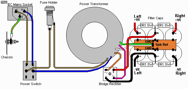
If I were to use a two cap bank right behind the bridge consisting of two 15kuF caps and then connect them to each board containing two 15kuF caps by way of 0r1 5W resistors as shown in the picture, would I essentially have 22,500 uF per rail per channel? Would I see much improvement using a four cap bank instead? Depending on how good this amp sounds, it may end up driving my nearfields which are 4ohm Event 20/20 speakers. Being nearfields they are not driven too loudly. If it has enough headroom I may use it for my midfields which are JBL 4411's & 4425's which are 8ohm. I'm not sure yet what each amp will end up doing. The KSA 50 may fit in here somewhere. I'm planning on replacing all of my Haflers and Soundcraftsmen amps with these DIY amps. Then I can sell those to help pay for this wonderful hobby I've fallen into. 😀
As for the other question I asked, is there a benefit to running the front end with 70V rails and the outputs with 65V rails?
I suppose I will need a separate bank of filter caps for this. Can I get by with less uF for one of these banks?
Thanks, Terry
i have the board
arrived today.....
great job!!!
thank you....
but there's a little mistake....
the th/diode boards and the main board don't have cut for breaking......
I cut it handly...😀
arrived today.....
great job!!!
thank you....
but there's a little mistake....
the th/diode boards and the main board don't have cut for breaking......
I cut it handly...😀
Actually, there was some talk earlier in the thread about that the fact that the boards were not going to be scored or cut in order to save a little on the cost. But, as you can see, it's not a big deal...just need to break out the saw/dremel 😉
As for the BOM, I just wanted to ask about the 'TO BE DEFINED' resistor values...currently, I've just used the values that Dr. Leach recommends within his BOM for putting together my parts order. I don't see much reason for them to change, but I wanted to make sure before ordering. Thanks!
As for the BOM, I just wanted to ask about the 'TO BE DEFINED' resistor values...currently, I've just used the values that Dr. Leach recommends within his BOM for putting together my parts order. I don't see much reason for them to change, but I wanted to make sure before ordering. Thanks!
- Status
- Not open for further replies.
- Home
- Amplifiers
- Solid State
- Smaller Leach Amp V1