I came up with a novel way to build a ported box, and thought I'd share it with the forum. This method of building the ported box has a few advantages over a conventional build:
1) It is possible to make the depth very very shallow, without resorting to the use of an expensive 'shallow' subwoofer driver
2) This method of building a vented box makes the baffle more rigid
3) It is easier to build than most horns
4) It is potentially cheaper to build than a conventional ported box. (I'll explain why in a minute.)
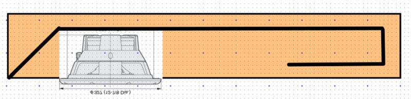
Here's a conventional ported box, using a slot port. In this pic, I've made the enclosure very wide and shallow. You might use a box shaped like this for a pickup truck, or for a home theater where you wanted to hide the subwoofer or use it as a false floor.
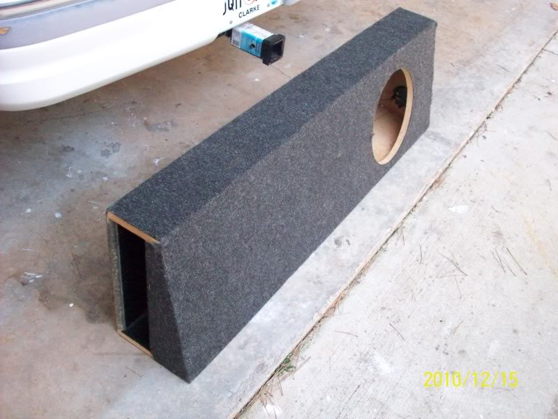
Here's an example of a ported box shaped like this.
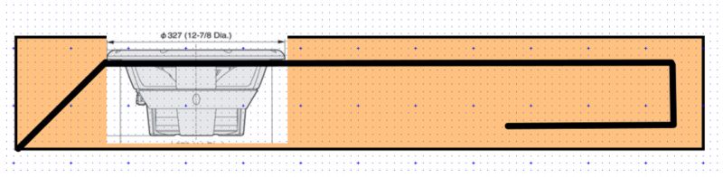
Here's my box.
The change in the box is very simple - I've taken the woofer and I've put it INTO the port. So the woofer is mounted in the port, instead of being mounted to the outside of the subwoofer box itself. By doing this, the depth of the box is about an inch shallower (because the woofer isn't mounted outside.) The box is a little bit cheaper to build, because you don't have to spend money on a grill. If you're using the subwoofer as a false floor or placing it behind a couch, you can push it ALL THE WAY against the wall, because the sound comes out of the SIDE of the box, not the FRONT of the box. The subwoofer baffle is more rigid, because it's bonded to the outside wall. (This assumes that you connect the inner and the outer wall with a brace.)
1) It is possible to make the depth very very shallow, without resorting to the use of an expensive 'shallow' subwoofer driver
2) This method of building a vented box makes the baffle more rigid
3) It is easier to build than most horns
4) It is potentially cheaper to build than a conventional ported box. (I'll explain why in a minute.)
Here's a conventional ported box, using a slot port. In this pic, I've made the enclosure very wide and shallow. You might use a box shaped like this for a pickup truck, or for a home theater where you wanted to hide the subwoofer or use it as a false floor.
Here's an example of a ported box shaped like this.
Here's my box.
The change in the box is very simple - I've taken the woofer and I've put it INTO the port. So the woofer is mounted in the port, instead of being mounted to the outside of the subwoofer box itself. By doing this, the depth of the box is about an inch shallower (because the woofer isn't mounted outside.) The box is a little bit cheaper to build, because you don't have to spend money on a grill. If you're using the subwoofer as a false floor or placing it behind a couch, you can push it ALL THE WAY against the wall, because the sound comes out of the SIDE of the box, not the FRONT of the box. The subwoofer baffle is more rigid, because it's bonded to the outside wall. (This assumes that you connect the inner and the outer wall with a brace.)
Last edited:


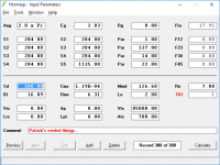
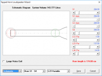
The only practical way to model this thing is to model it as a tapped horn. That's because the woofer is mounted inside of the port. I made an Akabak model, and the Akabak model was consistent with hornresp. The pic above illustrates how you model this. The mouth of the port is "S4." The woofer is mounted at "S3", just as in a tapped horn. The chamber of the vented box becomes the throat chamber of the horn. Basically the woofer is mounted inverted, with the basket IN the throat chamber.
Again, if none of this makes sense, I have an Akabak model that simmed very similar, so this method seems to be repeatable.

Here's the raw frequency response. That looks a little rough, but I'm using a woofer with a qts of 0.71, so it's hardly ideal for a ported box.


Here's the frequency response and displacement when using a high pass filter at 20hz, and a low pass filter at 110hz. It significantly flattens the response curve. Again, it's not perfect, but that's largely because I'm using a woofer with a qts of 0.71.
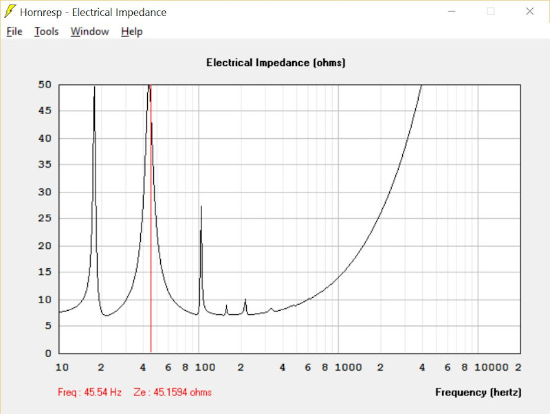
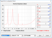
Here's the impedance curve. At 45hz, where there's a lot of content in movies and music, the woofer is loafing along at a very high impedance. Which should give the amplifier a break.
If your diagram is drawn to scale, I'd be concerned about the woofer blocking a bit too much of the port. Maybe if it's countersunk rather than mounted directly on the side panel...
Have you tried moving the woofer's location along the vent to see if that could minimize or eliminate the null that's appearing at just over 100 Hz?
Have you tried moving the woofer's location along the vent to see if that could minimize or eliminate the null that's appearing at just over 100 Hz?
Oh, try the "TH2" alignment in HornResp. With your existing choice of alignment, the drawing does not match the hornResp sim (the expansion starts at the driver's egdge, not its center).
Oh, the other problem you're going to run into with that design is that the woofer's pole vent is likely to be blocked too much (unless of course you use a woofer that does not have a pole vent 🙂. Now, if you can shift the woofer to be on the expanding section...
If your diagram is drawn to scale, I'd be concerned about the woofer blocking a bit too much of the port. Maybe if it's countersunk rather than mounted directly on the side panel...
Have you tried moving the woofer's location along the vent to see if that could minimize or eliminate the null that's appearing at just over 100 Hz?

Here's a measurement showing the measured response BEFORE THE BOX WAS FINISHED and the hornresp prediction.
I wanted to hold off on posting this, because the box isn't done, but the measurement illustrates that the high frequency response is fairly well behaved.
Here was my thought process:
The high frequency response of subwoofers is usually a lot smoother than hornresp predicts. And I figured that I could smooth out the response by mounting the woofer offset by the golden ratio. (Hornresp doesn't simulate in 3D, it simulates in 2D.)
I anticipate that the finished response will be much better. The measurement above has two issues. First, the box is sealed using clamps, not glue or screws. Second, I measured it in my garage, where it's really difficult to get a good measurement. Once the glue dries, I'll do a groundplane measurement outside, which will give a better idea of how it performs.
Note that both the simulated and the measured response is using a high and lowpass filter.
Oh, try the "TH2" alignment in HornResp. With your existing choice of alignment, the drawing does not match the hornResp sim (the expansion starts at the driver's egdge, not its center).
I have an Akabak model that's consistent with the diagram. To model it properly, you need five segments. (Hornresp only supports four.)
I haven't posted the Akabak model (yet) because the difference between Hornresp and Akabak was very subtle, and nobody uses Akabak 😉
Oh, the other problem you're going to run into with that design is that the woofer's pole vent is likely to be blocked too much (unless of course you use a woofer that does not have a pole vent 🙂. Now, if you can shift the woofer to be on the expanding section...
I wanted to make the design as simple as humanly possible.
I am using a woofer that I bought from Craigslist for $32.50, so I didn't want to do anything "fancy" like mounting the woofer on the expanding section.
I intentionally used cheap wood, because I wanted to see if it was possible to make a fairly decent performing home theater sub for under $100. Basically wanted to find out if I could exceed the performance of a 'Wal Mart' subwoofer using cheap drivers off of Craigslist, cheap wood, and easy construction.
I left a very very small gap between the pole vent and the wall, about 1/2". This isn't a high power sub; this is designed to be a cheap sub that can play 30hz, doesn't cost a lot of money, and is intended to be one sub of a subwoofer array.
I have an Akabak model that's consistent with the diagram. To model it properly, you need five segments. (Hornresp only supports four.)
I think it can be modelled in HornResp using the "TH1" alignment option, which puts the tap at S3 instead of S4. See below.
Attachments

hornresp predicts. And I figured that I could smooth out the response by mounting the woofer offset by the golden ratio. (Hornresp doesn't simulate in 3D, it simulates in 2D.)
Actually HornResp does a pretty good prediction of the response, up to the point where bends in the horn start to approach the wavelengths under consideration. Where you see differences start is where the sim doesn't match the build, or vice-versa. In this case, even modelling this as a TH1 alignment, there's still the issue of how the chamber is being modelled, which will cause a variation in predicted response curve. In this case, only slight variations in the value of Atc used in the sim produce huge differences between 100 Hz and 200 Hz.
Have you taken an impedance curve? That will show how close you've come to the sim.

Here's the predicted and the measured response of the subwoofer

I was a little concerned about the rolloff of the sub. It's rolling off faster than predicted. But the measured and predicted impedance curve are a (fairly) good match, so the rolloff seen from 20-40hz could have something to do with my microphone or my measurement technique.

Here's the predicted and the measured response with a high and low pass filter in place. In the measured response there are two curves. One is unequalized. The other is with 4dB of boost at 35hz. I wanted to see if the sub responded well to equalization, and it does. The impedance at 35hz is very high, so it seems like adding some boost there is a no-brainer.
Last edited:
It's difficult to compare sims vs. actual responses just from images, particularly if the graphs have different minimums and maximums for their axes.
I've got a simple workbook that makes the comparison simpler. Basically you just export the HornResp predictions to a data file, then copy that data to the appropriate spreadsheet in the workbook. Ditto for DATS measurements and measurements from HolmImpulse (though it can be jigged to support REW quite easily.
See example below - predicted vs. measured response for my B1 TH design.
Drop me an e-mail if you want a copy.
Note: higher impedance at low frequencies usually also means higher cone excursion for a given voltage input. Probably not the best place to apply a boost 🙂
Attachments

- Status
- Not open for further replies.
- Home
- Loudspeakers
- Subwoofers
- Smaller, Cheaper, Stronger