Small Syns 3d printed replacement waveguide
I thought I would put this here as to not clutter up the main Small Syns thread until they are done.
I am attempting to design a drop in replacement for the horn in the SmallSyns, as it is all but impossible to purchase it now. I'm hoping to just get it close, so no (or a very minor value change) is needed to drop into Bill's design.
The original horn was the SEOS15 sold by DIYSoundGroup, and designed over at AVS Forums by committee. The end product design work was done by jzagaja. Final specs were listed here, but there is a lot of wiggle room there. Later talks put the throat at 16deg with a small conical section before the transition to the OS profile. It reads like this was for the fiberglass horn, so I assume the plastic molded horn used the same profile.
I have never seen an SEOS15, so this should be fun.
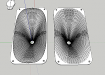
I have went through multiple dozens of designs, done in several different ways, and narrowed it down these two to try out. They were designed in two different series, and both are close. These are the targeting shots.
From left to right they are models 15b and 15bb3.
Polars shown with the same layout with Horizontal up top and Vertical on the bottom. No cd throat length added here.
The pink trace is 45deg. 5deg spread from 0deg on up.
Test measurements and explanations starting in post #15
I thought I would put this here as to not clutter up the main Small Syns thread until they are done.
I am attempting to design a drop in replacement for the horn in the SmallSyns, as it is all but impossible to purchase it now. I'm hoping to just get it close, so no (or a very minor value change) is needed to drop into Bill's design.
The original horn was the SEOS15 sold by DIYSoundGroup, and designed over at AVS Forums by committee. The end product design work was done by jzagaja. Final specs were listed here, but there is a lot of wiggle room there. Later talks put the throat at 16deg with a small conical section before the transition to the OS profile. It reads like this was for the fiberglass horn, so I assume the plastic molded horn used the same profile.
I have never seen an SEOS15, so this should be fun.
I have went through multiple dozens of designs, done in several different ways, and narrowed it down these two to try out. They were designed in two different series, and both are close. These are the targeting shots.
From left to right they are models 15b and 15bb3.
Polars shown with the same layout with Horizontal up top and Vertical on the bottom. No cd throat length added here.
The pink trace is 45deg. 5deg spread from 0deg on up.
Test measurements and explanations starting in post #15
Attachments
Last edited:
With luck one of these horns will be close enough.
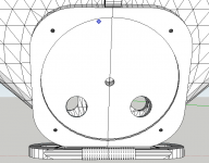
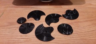
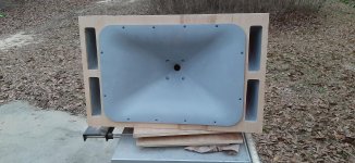
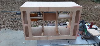
I have the first one (15b) printed out (draft quality in one piece with a .8mm nozzle) in low poly mode with the first two shots at the mid taps ready to go as well.
I have different tap locations on each side of the horn, and printed a few easily changeable plugs to dial in the mid chambers needed.
I didn't notice, but the edge showing doesn't have the brim completely pulled off. It is straight.
Attachments
Last edited:
I was looking at your print and I saw that the surfaces seem to be small rectangles. Is that what you mean with with draft mode? The kit is looking great. IMHO, you may need a little bit of extra with on the bottom flange, the screw mount looks to close to the final round over of the waveguide.
The large rectangles would be the low polygons count. It is faster to test tap positions with less geometry to deal with, the way I do it anyway... Once I am happy with placement I will transfer it over to the higher poly model.
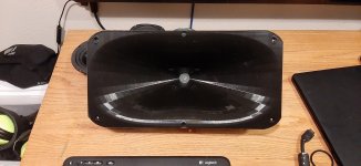
Draft mode is in reference to the speeds I printed at. It was as fast and hot as possible with my setup while still holding full surface integrity. There is ringing in the y axis and zits visible, but no under extruded or sagging areas. It isn't pretty, but the horn (especially the throat) is smooth and doesn't require any touch up for testing.
As you noticed the middle screw holes are technically in the mouth edge. When I first started designing the horns I was trying to stay away from a direct drop in, but once I realized I could print the whole horn at one time if I did, I came around. I just minimized the mounting surfaces to work with what I had already.
In this case there is a difference of a little less then 2mm from one side of the screw head opening to the other. I recessed the #6 pan head screws just enough for it to fill in the area slope pretty close. I will run a pass with the offending holes filled in as well to see how they effect things. I'm crossing my fingers that it is really too small to even show.
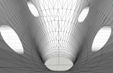
The lighting, large polygons, and glossy surface from printing hot makes the mouth look like it is terminating much faster than it is.
If I can get these to work I also have a split version mocked up for smaller printers, along with mid configurations of 2, 1, or none.
Draft mode is in reference to the speeds I printed at. It was as fast and hot as possible with my setup while still holding full surface integrity. There is ringing in the y axis and zits visible, but no under extruded or sagging areas. It isn't pretty, but the horn (especially the throat) is smooth and doesn't require any touch up for testing.
As you noticed the middle screw holes are technically in the mouth edge. When I first started designing the horns I was trying to stay away from a direct drop in, but once I realized I could print the whole horn at one time if I did, I came around. I just minimized the mounting surfaces to work with what I had already.
In this case there is a difference of a little less then 2mm from one side of the screw head opening to the other. I recessed the #6 pan head screws just enough for it to fill in the area slope pretty close. I will run a pass with the offending holes filled in as well to see how they effect things. I'm crossing my fingers that it is really too small to even show.
The lighting, large polygons, and glossy surface from printing hot makes the mouth look like it is terminating much faster than it is.
If I can get these to work I also have a split version mocked up for smaller printers, along with mid configurations of 2, 1, or none.
Very nice, what 3D printer do you have? (prints look great)
Any thoughts about going beyond the seos design (if there are indeed improvements to be made)? (I notice that PB has more complex than the normal entry ports perhaps this is something to persue?)
Any thoughts about going beyond the seos design (if there are indeed improvements to be made)? (I notice that PB has more complex than the normal entry ports perhaps this is something to persue?)
I have never seen the low polygon count, but makes perfect sense. Your high speed print has no warps or cracks, so pretty good. I assume it is pla. I like the spilt version like bwaslo did in one of his projects.
I have the same keyboard as yo udo , I took out my 16" qsc/b52 waveguide to see if it was the same size. Just for your reference, the flat part of the inner flange is 1" wide.
Good luck geting the final model to work. Looking forward to see how it comes out.
I have the same keyboard as yo udo , I took out my 16" qsc/b52 waveguide to see if it was the same size. Just for your reference, the flat part of the inner flange is 1" wide.
Good luck geting the final model to work. Looking forward to see how it comes out.
kipman725, it is just a CR10 v2. I just took the time the adjust everything right out of the box, and then spent many evenings printing 3D Benchy over and over until I dialed in the settings.
I have ideas, but I have a few projects to clear away first.
Here there is not a lot more to get out of this form factor. In this case the 15b is OS from the throat with the vertical profile "squished" slightly to bump the horizontal directivity a little lower. The SEOS seems to do this by starting the entire OS transition a little further from the throat, and using a higher "q" as in mabats OS-SE equation. 15b should have better pattern control, but I played with the vertical mouth transition to trade for lower extension. The 15bb3 was done with the smoothest response in mind with a minor tweak to slightly lower HOR corner over the others in the bb series.
Mid taps are in this case going to mimic bwaslo's whatever it takes. The reflection notch needed isn't too high so it should be doable vanilla style. I think PB's more phase plug like taps are better suited for trying to push the mid upper corner over 2k, or with larger "mid" drivers, say >6". In both cases it would be to minimize tweeter interactions.
Frabor, it's Hatchbox PLA. Plenty of strength, just don't leave it away from an A/C for too long.
I like his large horn as well. Yet another WIP project thread forthcoming...
I have flat mounting sections on the rear of 18mm on the top and bottom, and 22.25mm on the left and right.
I like his large horn as well. Yet another WIP project thread forthcoming...
I have flat mounting sections on the rear of 18mm on the top and bottom, and 22.25mm on the left and right.
Attachments
Last edited:
Kevmoso, I'm quite fond of it myself. I has a kind of an active faceted reflection in person. I figured I would be the only one.
Last wg as clone? Im in florida. Pla left in the car will get ruined. On my side hustle we have used abs for prototypes, but the quality is aweful. we use shapeways for masters after prototypes and then cast on resin. I was wondering if you ever used petg, i just printed two small augerpro waveguides, but have not print anything substantial is size.
Last edited:
I do not want to make a clone.
That's why originally I was using totally different dimensions. I changed my mind on the differing dimensions to allow myself to print them in one piece, and it allows the original build plans to be used as.
Throat, profile, mouth, and corners all mine. Height, width, depth the same for using original build plans and depth also for phase.
I have used PETG. It isn't hard to print, and it works like PLA just use a slightly higher nozzle temp and a little more retraction needed. It will never be as smooth, or as strong as PLA. Joining and painting is also a pain. It will live happily in a garage or outside, but not in a FL car for more than a few days I would think.
Have you tried ASA instead of ABS. It should handle the heat, and is easier to print. You still need an enclosure, but warping and finish is supposed to be much better than ABS. I haven't used it yet, but that is the direction I will go when the need arises.
I have always wanted to try casting out, but I always talk myself out of it.
I may have read that wrong.
The horn in post 9 is bwaslo's large horn. It the woofer deleted version so that the woofers can be pushed further apart to get the array effect to push the directivity lower. I'm just doubling the woofer section for SPL and an easier ohm load. My friend is going to use it as a center powered by an avr.
The horn in post 9 is bwaslo's large horn. It the woofer deleted version so that the woofers can be pushed further apart to get the array effect to push the directivity lower. I'm just doubling the woofer section for SPL and an easier ohm load. My friend is going to use it as a center powered by an avr.
Yes , I was referring to the one in 9, looks very close to the qsc and I assumed it was your design not bwaslo. I guess this is the one that was printed by bwaslo two parts and screw together.
So it seems that both pla and petg, when it comes to florida, are home boys; they cannot live outside of in a car. Final solution is to cast them and make them in epoxy, but at this sizes, it will be a PITA. My coworker was telling me that a whole baffle with waveguide can be easily molded in fiberglass.
Will check ASA, sounds promising. Tks.
Last edited:
I ended up working on dirt bikes and go karts instead of my new polar pedestal as I had planned, but that is life.
I did manage to get a few preliminary measurements though.
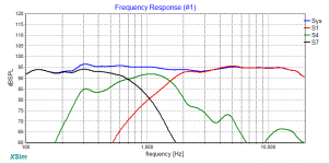
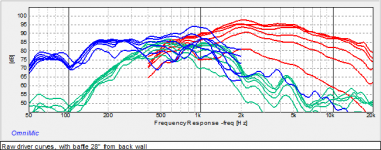
These are all the target images from the small syns thread that I am trying to recreate.
The directivity is the ran at 0, 20, 30, 45, 60, 90
I did manage to get a few preliminary measurements though.
These are all the target images from the small syns thread that I am trying to recreate.
The directivity is the ran at 0, 20, 30, 45, 60, 90
Attachments
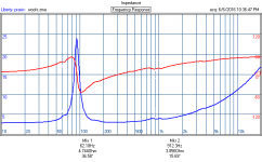
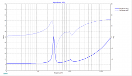
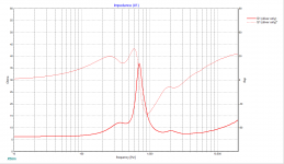
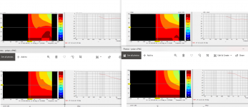
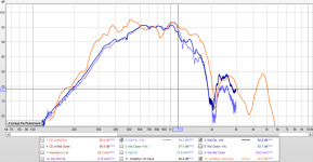
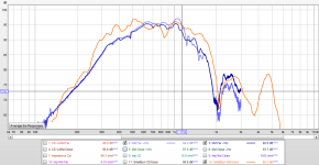
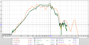
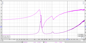
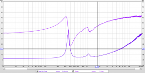
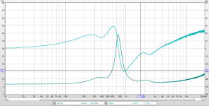
Here are a few quick and dirty measurements.
My IMP jig seems to be showing it's age as there is a little fuzz in the higher frequencies, but it works here.
These are taken with the CD, but with no baffle. This means they roll off a little early. I didn't think of a fix until later, and wasn't going to do them over due to time constraints. The mids are tested separately with cheap duct tape covering the non-tested holes, as the cheap stuff peels off easier. 😀
They were both tested with the base model mid chamber (+Vtc,) and with the max filler plug I had (-Vtc.)
I also added the 0deg raw polar Mid trace from the original thread that was added as a target above.
Looks like the Far and Close ports fell right above and below the needed 1/2 wavelength null. This makes final placement a lot smoother.
As shown, the notch at ~1.5k still needs to be brought up a lot. I shows the ports area are too large and will need to be made smaller as the mid chamber is already about a small as possible. Lengthening the port could also do it, but there isn't much play there. The question now is play dough or wood filler?
There is also the option of aggressively adding camber volume to raise the two notches below and use the bandpass upper corner to rub the 1.5k notch out. I haven't tried it before, but it should work after a fashion. I'll print up a spacing ring to test it out later.
The first set is real SPL, and the second is with the two matched to show the end result change more clearly.
Attachments
Last edited:
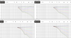
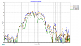
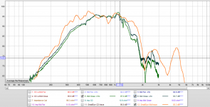
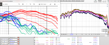
These are just fast passes to make sure things are going in the right direction. I didn't adjust the windowing here so ignore the fuzz. Once I finish my new measurement tower things will get more serious.
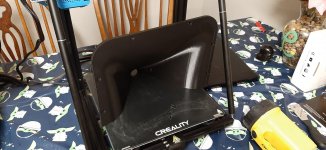
After a few unsuccessful attempts to get usable baffle free CD and polar test measurements I came up with a dumb idea.
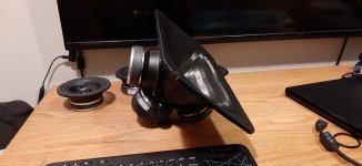
I used my old SmallSyns H290B test speaker turned around backwards as a stand on the base of my WIP polar rig (bucket pictured not part of polar rig.) It is the same size as the sealed SS, so it should work horizontally with the new horn sitting up top right on the edge, right?
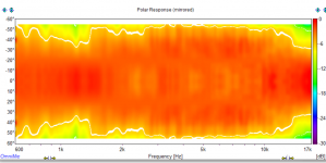
The directivity on the target was ran at 0, 20, 30, 45, 60, 90. I did 0 to 55 at 5deg steps, so I have 55 instead of 60.
I used SplTrace to add the 0deg run from the target to the REW chart, same as before.
The polar map is smoothed 1/24th and normalized to 20deg. It looks like a SEOS 15 & 18 love child.
The Imp is no baffle. I didn't redo it. These are just tests.
After a few unsuccessful attempts to get usable baffle free CD and polar test measurements I came up with a dumb idea.
I used my old SmallSyns H290B test speaker turned around backwards as a stand on the base of my WIP polar rig (bucket pictured not part of polar rig.) It is the same size as the sealed SS, so it should work horizontally with the new horn sitting up top right on the edge, right?
The directivity on the target was ran at 0, 20, 30, 45, 60, 90. I did 0 to 55 at 5deg steps, so I have 55 instead of 60.
I used SplTrace to add the 0deg run from the target to the REW chart, same as before.
The polar map is smoothed 1/24th and normalized to 20deg. It looks like a SEOS 15 & 18 love child.
The Imp is no baffle. I didn't redo it. These are just tests.
Attachments

Last edited:
- Home
- Loudspeakers
- Multi-Way
- Small Syns 3d replacement waveguide