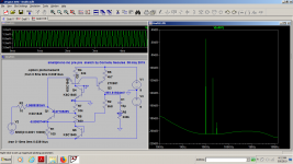
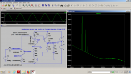
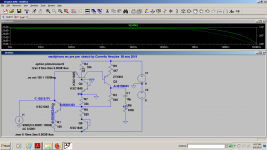
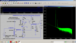
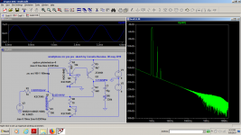
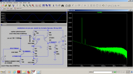
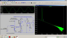
Being "inspired" by a current amplifier circuit i saw in an old book for students i thought of giving it a try for an mc pre pre...at least for fun.
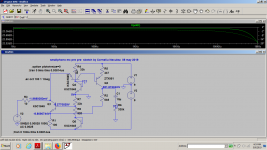
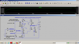
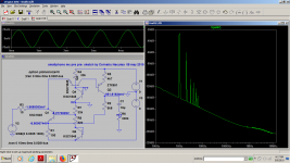
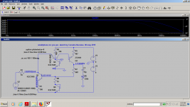
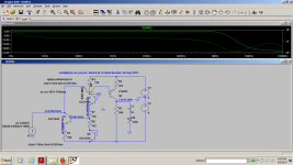
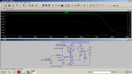
The THD look like valve usual thd , but what i don't really understand is how the feedback works or if it works at all at ac as you might see that i have almost the same thd figures and bode plot with current feedback as in voltage feedback.I tried 0.1mv, 0.25mv and 2.5mv at 1khz, 10khz and 1...100mHz for the bode plot.
Indeed this looks like a current amplifier
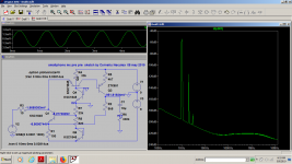
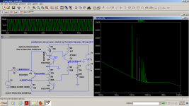
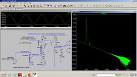
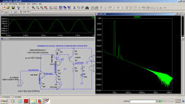
I even modified all the values almost randomly and all the time i have 60...65db THD no matter the output unless it's very high.
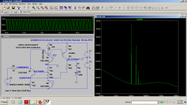
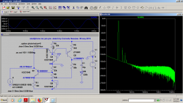
Everything changes when i define the input as current and the THD drops significantly in current feedback compared to VFB.It is a current amplifier basically, so it needs lower impedance sources but the 10 ohms was too high...
To be honest i don't understand this circuit...I just did it for exploration...
The THD look like valve usual thd , but what i don't really understand is how the feedback works or if it works at all at ac as you might see that i have almost the same thd figures and bode plot with current feedback as in voltage feedback.I tried 0.1mv, 0.25mv and 2.5mv at 1khz, 10khz and 1...100mHz for the bode plot.
Indeed this looks like a current amplifier
I even modified all the values almost randomly and all the time i have 60...65db THD no matter the output unless it's very high.
Everything changes when i define the input as current and the THD drops significantly in current feedback compared to VFB.It is a current amplifier basically, so it needs lower impedance sources but the 10 ohms was too high...
To be honest i don't understand this circuit...I just did it for exploration...
Attachments
-
 prepre1.png78.8 KB · Views: 168
 -
 preprebode-1Mhz.png67.5 KB · Views: 71
 -
 mcprepre1khighbode.png66.6 KB · Views: 55
 -
 mcprepre1kmedium bode.png66.5 KB · Views: 60
 -
 mcprepre1klowbode.png66.1 KB · Views: 57
 -
 mcprepre 1k-low.png77.4 KB · Views: 57
 -
 mc-prepre 1k-medium.png75.7 KB · Views: 156
 -
 prepre1k-high.png76.8 KB · Views: 155
 -
 mcprepre10k-high.png81.2 KB · Views: 166
 -
 prepre10k-2.png77.2 KB · Views: 168
Last edited:
the rest of the photos
Attachments
-
 preprecfbbode100Mhz.png67.7 KB · Views: 71
 -
 preprecurrentinCFB10khz.png85.3 KB · Views: 60
 -
 pre-pre currentinputCFB.png79.9 KB · Views: 51
 -
 currentinput.png75.6 KB · Views: 52
 -
 mc pre-prevfb.png79.1 KB · Views: 54
 -
 mcpreprevfbbode1.png65.3 KB · Views: 58
 -
 preprebodeplot-100Mhz.png66.3 KB · Views: 69

Hi,
I´d replace R8/Q6 by a red LED, thermally coupled to Q1 to form a stable current source.
Drawn as is, the current varies with supply voltage and Ypu don´t want varying bias points right at Your delicate cartridge.
jauu
Calvin
I´d replace R8/Q6 by a red LED, thermally coupled to Q1 to form a stable current source.
Drawn as is, the current varies with supply voltage and Ypu don´t want varying bias points right at Your delicate cartridge.
jauu
Calvin
I'm not even sure if it really works in real life noisewise, it was just a quick exercise picked up from a book with transistors topology explained to students.It looked interesting to me...There are some more interesting circuits in that book inspired probably from Sedra, but a bit different.Unfortunately i can't find my Sedra book...
I wouldn't probably risk any mc cart on this anyway.
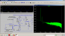
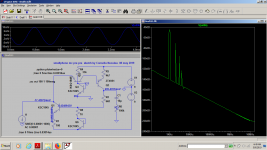
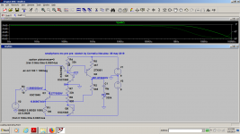
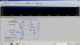
Just some other sims that show no need of feedback with this circuit at these low levels:
I wouldn't probably risk any mc cart on this anyway.
Just some other sims that show no need of feedback with this circuit at these low levels:
Attachments
🙂Thats the most obfuscated way I've seen to draw two current mirrors!
- Status
- Not open for further replies.
- Home
- Source & Line
- Analogue Source
- small sketch for a pre pre mc cartridge