Hello all,
Sorry If I'm posting this in the wrong place (new here).
I recently built a couple of these preamps for a spring reverb project I'm working on:
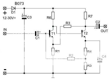
R1 = 560 Ohm
R2 = 160K Ohm
R3 = 47K Ohm
R4 = 560 Ohm
R5 = 560 Ohm
R6 = 68K Ohm
R7 = 2.7K Ohm
C1 = 1uF
C2 = 1uF
C3 = 220uF
C4 = 47uF
One of them is being used as the recovery buffer for the reverb tank, but as the output of the tank is quite low (even with a 3W amp driving it) I would like to increase the gain of the preamp, I'm guessing around 50% but any amount of extra gain would be useful.
Can anyone point me in the direction of where and how to make the the necessary changes to achieve this if it's even possible?
Thanks
Sorry If I'm posting this in the wrong place (new here).
I recently built a couple of these preamps for a spring reverb project I'm working on:
R1 = 560 Ohm
R2 = 160K Ohm
R3 = 47K Ohm
R4 = 560 Ohm
R5 = 560 Ohm
R6 = 68K Ohm
R7 = 2.7K Ohm
C1 = 1uF
C2 = 1uF
C3 = 220uF
C4 = 47uF
One of them is being used as the recovery buffer for the reverb tank, but as the output of the tank is quite low (even with a 3W amp driving it) I would like to increase the gain of the preamp, I'm guessing around 50% but any amount of extra gain would be useful.
Can anyone point me in the direction of where and how to make the the necessary changes to achieve this if it's even possible?
Thanks
Can anyone point me in the direction of where and how to make the the necessary changes to achieve this if it's even possible?
Change R3 to 100k. This should double the gain (+6dB) if the circuit is adequate.
Change R3 to 100k. This should double the gain (+6dB) if the circuit is adequate.
Thanks very much for the advice; I've made that modification and it made a noticeable difference.
Thanks very much for the advice; I've made that modification and it made a noticeable difference.
If you want to play around a little more, replace the C1 and C2 electrolytics with 10uF 50V bipolar types.
Also, use a 100uF 50V bipolar for C4. If you hot plug, you might want a resistor to ground at the input and output
to avoid pops. A 100k resistor in both places should be ok.
Last edited:
Basically yes, although that preamp is already close to max gain as is.
What I don't get is the suggestion to use bipolars there, besides the inconvenience of finding them and the higher price.
Also 10uF output cap is fine, but 10uF input is way too high, even more in a reverb circuit.
As is, 1uF has a cutoff frequency of about 3 Hz ; why go lower?
In fact I would use a much smaller one, say .1uF or .047uF .
I suspect the reverb tank might be poorly driven, because of improper impedance matching to the driver amp.
What brand, model and code is the reverb tank?
What characteristics does the "3 W" amp have?
You might post the full schematic 😉
Would increasing the value of R3 even more give me yet more gain, or is 100k going to give the max amount of useful gain in that department?
JMFahey, you may well be right about the impedance mismatch. As I couldn't find any technical info on the reverb tank, I decided to wing it and hope for the best.
The tank is an old OC electronics Folded Line type 51. The amp is a Kemo M031N. It's a sealed unit, and there is no schematic on their site for it, although it does say it can drive a 4-16 Ohm load.
M031N Amplifier 3,5 W, universal
My knowledge of electronics is quite basic so I do appreciate the help a lot.
Thanks!
An externally hosted image should be here but it was not working when we last tested it.
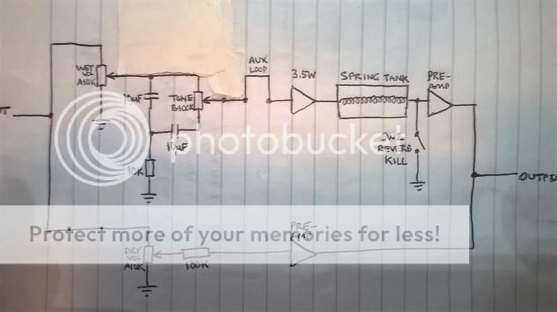
this is a crude drawing of the circuit at the moment (sorry it's not very clear). Both the preamps are as shown in the schematic in my original post, except the one after the reverb tank now has the 100k resistor for R3.
The reverb level is not too bad, but still a little too quiet for my liking compared to the dry signal (which itself is not particularly loud). I don't want to overwork the driver amp or damage the tank's input coils.
I was considering adding a feedback control if I can get the other issue fixed, to maybe get some interesting effects and provoke a little resonant ringing (I know this is something people usually want to avoid, just a little experimentation). My trial and error method of trying to implement the feedback pot has not been successful! Probably due to not knowing what I'm doing.
POk.
You seem to have this one:

I have seen "Type": 51 - 76 - 247 ;there are probably others.
Reverb tanks in general have a drive coil and an output coil.
Output in general is as high an impedance as possible, to get maximum signal voltage; now impedance must match the drive mini power amplifier for maximum power transfer, not the same.
So tanks were made in very different combinations to suit manufacturers.
The point is that your amp is 3.5W into 4 ohms ... if the tank input is 60 - 160 - 600 ohms maybe it's using just a few milli-watts 🙁
OC Electronics flailed, was bought by Accutronics some 40 years ago and those codes were lost, but a tank is a tank.
Please measure the DC resistance of the input and output coil and post it here, we might compare it to the current Accutronics (or Belton, who bought it) impedance chart:

Only then I can suggest you some preferred circuit.
You seem to have this one:
I have seen "Type": 51 - 76 - 247 ;there are probably others.
Reverb tanks in general have a drive coil and an output coil.
Output in general is as high an impedance as possible, to get maximum signal voltage; now impedance must match the drive mini power amplifier for maximum power transfer, not the same.
So tanks were made in very different combinations to suit manufacturers.
The point is that your amp is 3.5W into 4 ohms ... if the tank input is 60 - 160 - 600 ohms maybe it's using just a few milli-watts 🙁
OC Electronics flailed, was bought by Accutronics some 40 years ago and those codes were lost, but a tank is a tank.
Please measure the DC resistance of the input and output coil and post it here, we might compare it to the current Accutronics (or Belton, who bought it) impedance chart:
Only then I can suggest you some preferred circuit.
My tank is identical to the one you posted. I've done as you suggested, and interestingly the input and output resistances are almost equal:
I/P = 176.5 Ohm, O/P = 179.5 Ohm
I remember taking those measurements when I first got the tank, but from what I'd read that would still not determine the true impedance.
I hope there's some way get the amp and the tank to play nicely together as the physical size of the amp is perfect and the tank has a great sounding reverb.
Thanks
Ok, it's a High in High out reverb, the most popular today because it's easy to drive and recover with a single U$0.50 Op Amp .
Everybody uses the same basic circuit, which is just a tweak of the generic one posted by Accutronics itself.
Just build this one, it does work, it was one of my first commercial products since 1969 , I built hundreds of them.
It specs a High/High Hammond/Gibbs/Accutronics/Belton reverb tank and will make a perfect match with your particular GC tank:
Popular Electronics January 1968
the basic circuit:
you'll need the modern equivalents for those obsolete transistors.
The extra article feature is that they explain how to feed and adapt it for SS and tube transistors.
Everybody uses the same basic circuit, which is just a tweak of the generic one posted by Accutronics itself.
Just build this one, it does work, it was one of my first commercial products since 1969 , I built hundreds of them.
It specs a High/High Hammond/Gibbs/Accutronics/Belton reverb tank and will make a perfect match with your particular GC tank:
Popular Electronics January 1968
the basic circuit:
An externally hosted image should be here but it was not working when we last tested it.
you'll need the modern equivalents for those obsolete transistors.
The extra article feature is that they explain how to feed and adapt it for SS and tube transistors.
JMFahey, thanks again for your response. I'm really glad that someone with so much first-hand spring reverb experience is able to help me out. In case it's not obvious, this is my first one. Just learning as I go along 🙂
I haven't been able to "throw it together" like I first imagined when I decided to make one, but it's been a lot of fun so far.
OK, so unfortunately it seems my little sealed amp is a bad match for the tank, which is unfortunate. Hopefully it'll get used somewhere else, maybe with a 10 Ohm Accutronics tank in the future.
Building the circuit you kindly posted is an attractive option. My only concern is that the article mentions that approximately 30V is needed to run it. I am hoping to power everything on 12V. With the modern equivalent transistors in place, would 12V be adequate? If so would I have to change the value of R12?
What kind of 12V are we talking about?
Some raw 12V which will need to be further filtered and cleaned up 9so we'll end with , say, 10V) or the output of, say, a 7812 regulator which is very clean and ripple free so can be used in full without further processing?
In general, being a high impedance tank we need a relatively high supply so we can drive it with a higher audio signal; but it can be adapted to a 12V supply, only reverb will be somewhat weaker.
Any reason you are *forced* to use just 12V?
What are the power rails of the amplifier you'll use?
PS: that project showed an add on module to existing amplifiers, they mention 2 of them with 30 or 40V rails, two months later they published a 60W guitar amp fed from single 60V and in the article they mention how to add the module to *Tube* amps, having 300 to 500V supplies.
What will you use it with?
Can't you make a higher voltage supply?
The power supply I was intending to use is just a standard "wall wart" type regulated 12V supply rated at 2A. I am by no means forced to use it, and can find another supply for this project. I thought the preamp I have for the dry signal wouldn't work on 30V but as it happens, 30V is the max it can take.
The reverb unit will be a standalone box with an input and output jack for various audio signals, so not directly connected to any amplifier. It will be powered by its own external power supply.
Am I right in thinking that if I supply ~30VDC directly to the circuit, R12 can be omitted altogether? I'm also unclear on how the values of R14 and R15 will be affected, given that the system is a self-contained reverb unit.
I have ordered the capacitors and transistors to build it. The article recommends that 1/2W resistors should be used, however I have all the values required in 1/4W rated metal films already. Do you think these would survive in the circuit or are 1/2W resistors absolutely necessary?
- Status
- Not open for further replies.
- Home
- Design & Build
- Construction Tips
- Small PCB preamp - how to adjust gain?