maybe that is what I say previous about R11 side effect.I'm not sure, but R11 may be there to speed up charging of cap c3. My guess that at turn on there might be some voltage on the output and the 1K resistor will speed up the charging (or discharging) of the coupling cap. As Mooly pointed out - it shouldn't make any difference at audio frequencies - just very low frequencies. It may adversely affect DC offset, though.
 surely I can't remember😱
what is the bennefit by speed up charge/discharge C3?😕
Last edited:
while C4 (phase lead cap?) limiting the bandwidth, Miller cap limiting the slew rate?increasing the Miller comp cap to match the same stability criteria as the combined Miller + lead comp cap, you should find that the big Miller comp cap (as Self) introduces less distortion.
That smaller lead cap combined with a smaller or no Miller comp cap will sound different.
I hope my use of "lead cap" for the VAS to -IN cap is correct.
isn't better to use smaller Miller cap to increase slew rate, so lesser non-linear distortion at hi freq, but limit the bandwidth by C4 to maintain stability?😕
or better to use "suitable" Miller cap to match slew rate vs bandwidth (for maintain stability issue even further) ? 🙄
An externally hosted image should be here but it was not working when we last tested it.
Slew rate nomograph from Elliott Sound Products - Audio Power Amplifier Design Guidelines
changing the Vas transistor with video transistor is it realy worth the effort?😕
I heard many times that change the Vas transistor with video transistor will reduce distortion (or the like ), as a video Tr has realy high fT and low Cob...😱
I heard many times that change the Vas transistor with video transistor will reduce distortion (or the like
), as a video Tr has realy high fT and low Cob...😱This modification made Fokker amplifier square wave much better
The distortion have reduced from 0.018% to 0.006% (THD)
Was assembled and the sonic result is clear..you can listen in the treble range.
Many thanks Kroto...you came as a messenger from the heaven...exactly in the moment i was needing....good!
Left is the 20 kilohertz oscilogram with Kroto's modification, the rigth side one is without Kroto modification
regards,
Carlos
Attachments
Last edited:

ha ha ha, thanks Carlos, another big input.
Hugh Dean will also agree too.
if I wasn't wrong its in AKSA55, he say that "Vas transistor must brutaly fast...".
Hugh Dean will also agree too.
if I wasn't wrong its in AKSA55, he say that "Vas transistor must brutaly fast...".
maybe that is what I say previous about R11 side effect.
what is the bennefit by speed up charge/discharge C3?😕
Did you mean R10 instead of R11? (referring to post 1) R11 helps set the range of bias via Vbe multiplier, Q7. R10 creates a zero with C4, nothing to do with C3. C3 is the AC path, or DC blocking cap.
Oh and yes, I agree using a faster device for VAS with less compensation certainly yields better results, measurement wise. More BW = more accuracy.🙂
Last edited:
I do not know if Aksa is using something alike or not
Aksa has their own secrets....i have assembled and the schematic was destroyed, avoiding, this way, to have them in my computer files.
So, i do not know what Aksa is using..in the reality, it is better not to know.... because knowing i cannot copy... and not knowing, if i discover by myself, then i can use.
regards,
Carlos
Did you mean R10 instead of R11? (referring to post 1) R11 helps set the range of bias via Vbe multiplier, Q7. R10 creates a zero with C4, nothing to do with C3. C3 is the AC path, or DC blocking cap.
Oh and yes, I agree using a faster device for VAS with less compensation certainly yields better results, measurement wise. More BW = more accuracy.🙂
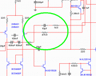
hi CBS240, sorry for the misconception😛
its(R11) in this circuit
An externally hosted image should be here but it was not working when we last tested it.
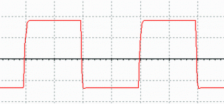
I will simulate again with lower freq to know the effect clearly.
this is in 20Hz
this is in 10Hz
*Red = without R11
*Green = with R11
from what I see, in the begining, peak voltage is always more lower than without R11.
and also the phase is shifting more.
if that so, is R11 used to minimize "pop" when turn ON/OFF?
while the side effect is shifting phase and lower peak voltage (at low freq)?
😕😕😕
An externally hosted image should be here but it was not working when we last tested it.
this is in 10Hz
An externally hosted image should be here but it was not working when we last tested it.
*Red = without R11
*Green = with R11
from what I see, in the begining, peak voltage is always more lower than without R11.
and also the phase is shifting more.
if that so, is R11 used to minimize "pop" when turn ON/OFF?
while the side effect is shifting phase and lower peak voltage (at low freq)?
😕😕😕
😱wow😱Betul benar, Mas Kroto......
Hugh
I don't know if you can speak Indonesian, but you will get C-😀😀😀 as betul (correct) and benar (true) is similar and no need to be repeated... 😀wewkkkkwewekew😀
but I'm sure my English will get D-...😛
Symetrical Amp
the circuit :
this is the current from Q5/Q6 (without R18/R19)
*green = Q6
*blue = Q5
this is the current from Q5/Q6 (with R18/R19)
*green = R19
*blue = R18
*brown = Q6
*cyan = Q5
this is the current from Q5/Q6 with CCS 10mA
*green = CCS replacing R19
*blue = CCS replacing R18
*brown = Q6
*cyan = Q5
I don't quite understand to read the graph, but is it worth the effort to add resistor/CCS to the Vas collector load?
is it make the Vas in more Class-A thing?😕
this one (mod) discovered by my self 😀 (maybe😱)Aksa has their own secrets....i have assembled and the schematic was destroyed, avoiding, this way, to have them in my computer files.
So, i do not know what Aksa is using..in the reality, it is better not to know.... because knowing i cannot copy... and not knowing, if i discover by myself, then i can use.
regards,
Carlos
the circuit :
An externally hosted image should be here but it was not working when we last tested it.
this is the current from Q5/Q6 (without R18/R19)
An externally hosted image should be here but it was not working when we last tested it.
*green = Q6
*blue = Q5
this is the current from Q5/Q6 (with R18/R19)
An externally hosted image should be here but it was not working when we last tested it.
*green = R19
*blue = R18
*brown = Q6
*cyan = Q5
this is the current from Q5/Q6 with CCS 10mA
An externally hosted image should be here but it was not working when we last tested it.
*green = CCS replacing R19
*blue = CCS replacing R18
*brown = Q6
*cyan = Q5
I don't quite understand to read the graph, but is it worth the effort to add resistor/CCS to the Vas collector load?
is it make the Vas in more Class-A thing?😕
distortion simulation
🙁 seems to be no one interested.
I've been simulating about R18/R19 addition to the circuit.
input added with 2nd Harmonic 0,1% (1mV sine@2kHz) distortion to the input signal (1V sine@1kHz)
without those resistor, distortion is 0,233947%
with those resistor installed, distortion is 0,140052%
oddly enough is by using an active current sink, distortion rises compared with only a resistor.
Bootstrap 0,147353%
CCS 0,234924%
any idea?
Last edited:
optimized value
R18; R19 = 5k6
DZ = 20V
addition of C6 (discharge cap)
distrotion is now 0.106437%
😉
An externally hosted image should be here but it was not working when we last tested it.
R18; R19 = 5k6
DZ = 20V
addition of C6 (discharge cap)
distrotion is now 0.106437%
😉
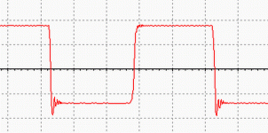
square wave
20kHz squarewave
rise time = 594 nS
fall time = 510 nS
😛
An externally hosted image should be here but it was not working when we last tested it.
20kHz squarewave
rise time = 594 nS
fall time = 510 nS
😛
further, R18 and R19 gives nothing differences (tiny bit) to the distortion performance after I change the Zener from 2v7 to 20V (to give more headroom).🙁
Open loop gain etc.? I'm not skillful with my sim...😛
Connecting the Miller cap to Gnd and changed to 220p (like Wahab amp) makes the square wave ringing so badly with or witout R18;19 in this scheme, moreover if the load were capacitive.
chao...
Open loop gain etc.? I'm not skillful with my sim...😛
Connecting the Miller cap to Gnd and changed to 220p (like Wahab amp) makes the square wave ringing so badly with or witout R18;19 in this scheme, moreover if the load were capacitive.
chao...
balance of LTP
some odd about the front end.
Q5 & Q6 determine the currents in R3 & R4b to ~1mA each.
That is then the Ic of Q1 and Q3.
Ir5 and Ir6 are about 19.5V / 1000 ~19.5ma.
The currents in Q2 & Q4 are about 19.5-1~18.5mA
How can you refer to these Q1+2 & Q3+4 as long tail pairs when the difference in current between the two halves of the pairs is ~17.5mA?
Hi...
I'm so sorry, I think yesterday my brain has shorted
running out of time and forgotten to change R5;R6 value...😱
after R5;R6 changed to 10k, distortion just rises to 0.323526% with R18;R19 installed. without it distortion is 0.142665%.
and if I use CCS (8mA), distortion down to 0.110260%.😀
thats better, thanks Andrew😛
must go now, running out of time again...
regards
- Status
- Not open for further replies.
- Home
- Amplifiers
- Solid State
- Small mod, what is the effect?