Hi all,
I have seen some amp that unusual.
I'm curious with it, this is some of it :
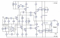
what is C4 doing in there? connected between Vas Collector load and inv-input. (somebody say it was a phase-lead feedback cap)
is it increase stability?
is it the same if C4 placed in parallel with R3?
I simulate that and found that the signal is shifting, is it good?.
* green = without C4 ; red = with C4 installed
* input signal is sinewave 50kHz@1Vp.
Oh, and also, there is now R11, connected in parallel with the NFB resistor.
what is the bennefeit of such that feedback?
with R11 installed in there, the output signal is about 1V higher.
is it good? or bad?
thanks folks,,, 😉
I have seen some amp that unusual.
I'm curious with it, this is some of it :
what is C4 doing in there? connected between Vas Collector load and inv-input. (somebody say it was a phase-lead feedback cap)
An externally hosted image should be here but it was not working when we last tested it.
is it increase stability?
is it the same if C4 placed in parallel with R3?
I simulate that and found that the signal is shifting, is it good?.
An externally hosted image should be here but it was not working when we last tested it.
* green = without C4 ; red = with C4 installed
* input signal is sinewave 50kHz@1Vp.
Oh, and also, there is now R11, connected in parallel with the NFB resistor.
An externally hosted image should be here but it was not working when we last tested it.
what is the bennefeit of such that feedback?
with R11 installed in there, the output signal is about 1V higher.
is it good? or bad?
thanks folks,,, 😉
Well this looks a lot like a rehash of Doug Selfs "blameless class B" design.
R11... should have no effect (it is not in parallel with the feedback resistor). The only reason it may do is at frequencies where the reactance of C3 is becoming high (in other words at LF). If you connect the end of R11 to the other end of C3 the effect should be zero.
C4 introduces hf feedback, here that signal is taken from the VAS stage rather than the output as in D Selfs original. It a valid approach.
Edit... I also see ground lift resistor R18. That also causes undesirable effects with R11 feeding into the input ground. Short out R18 and run your simulation again.
Last edited:
Thanks Mooly,
I will simulate again tomorrow, time to sleep now...
by the way, is C4 gives better stability?
I will simulate again tomorrow, time to sleep now...
by the way, is C4 gives better stability?
Member
Joined 2009
Paid Member
Well this looks a lot like a rehash of Doug Selfs "blameless class B" design.
.
It s a LIN topology with a current mirror.
It makes me always jump when i read that these
kind of topology is from douglas self, since he
invented none of the topologies that are in use
to this day...
I see,,,🙄C4 may allow you to use a smaller C6. Some people prefer that.
my friend have been built such amp with "C4", he use the same value Miller cap, just the tail current is bigger (maybe twice), make it have higher slew rate isn't it? he also use a video transistor for the Vas (very high fT and low Cob), its still not oscillate though.

It s a LIN topology with a current mirror.
It makes me always jump when i read that these
kind of topology is from douglas self, since he
invented none of the topologies that are in use
to this day...
I'm not suggesting he did invent it... what he did do was analyse each aspect of the design and push the performance to pretty impressive limits.
Whether that delivers what folk want sonically is open to discussion, but you can't argue with his method, or the results obtained... well I don't think so anyway.
this is the R11 simulation graph:
* Vin = 20Hz@ 1Vp
* red = with R18 installed
* green = R18 shorted
* blue = without R11 and shorted R18
with or without R18 its make no big diffrences.
just the starting has lower amplitude with R11 installed.
Am I really need R11 in there?
or the R11 value need to be lowered? like 100R?
or with similiar value with the Xc of C3 @ 20Hz?
and sorry for my bad english, I hope you know what I'm talking about.😀
An externally hosted image should be here but it was not working when we last tested it.
* Vin = 20Hz@ 1Vp
* red = with R18 installed
* green = R18 shorted
* blue = without R11 and shorted R18
with or without R18 its make no big diffrences.
just the starting has lower amplitude with R11 installed.
Am I really need R11 in there?
or the R11 value need to be lowered? like 100R?
or with similiar value with the Xc of C3 @ 20Hz?
and sorry for my bad english, I hope you know what I'm talking about.😀

Think about it 🙂
R11 is a 1k resistor.
The effect of that on loading the output stage is absolutely minimal.
So the only way that R11 can affect the amplifier is by the fact that it's feeding signal back into the input stage... which in a way is what you have with it connected to C3 as shown in the original diagram.
First... if you change the frequency to 20000 hz instead of 20 then the effect of C3 is reduced. Try that...
Secondly, connect the end of R11 to ground instead of to C3.
If it still alters the output then your simulation is wrong somehow 🙂
hi MoolyThink about it 🙂
R11 is a 1k resistor.
The effect of that on loading the output stage is absolutely minimal.
So the only way that R11 can affect the amplifier is by the fact that it's feeding signal back into the input stage... which in a way is what you have with it connected to C3 as shown in the original diagram.
First... if you change the frequency to 20000 hz instead of 20 then the effect of C3 is reduced. Try that...
Secondly, connect the end of R11 to ground instead of to C3.
If it still alters the output then your simulation is wrong somehow 🙂
no sim, just think now😀
"R11 is a 1k resistor.
The effect of that on loading the output stage is absolutely minimal."
it will be in parallel with the load, minimal effect, yes.
"First... if you change the frequency to 20000 hz instead of 20 then the effect of C3 is reduced. Try that... "
I've been try that before, because the effect is so small so I use 20Hz instead 20kHz, yes you're right.
connecting R11 to ground, back to the first term😀
seems like I've been read such mod in esp website, just I forgot where it is.
its have a bad effect also which I couldn't remember, do you know that effect?🙄
seems like I've been read such mod in esp website, just I forgot where it is.
its have a bad effect also which I couldn't remember, do you know that effect?🙄
🙂 Don't quite understand what you are asking.
R11 has a predictable effect depending on where you connect it... as you have found.
I have been expect that you gona say that,
is it the esp web (somewhere in the articles), or the bad effect?
I mean, in the past I've been read an article about R11 placement, which also had a bad habbit to the system, maybe when
operate abnormally?
this is my conclusion :
* C4 increase high freq stability, as it act as an integrator, right?
* R11 make a differentiator with C3 reactance.
do anyone have an explanation nor articles about C4 placement? why connected with Vas Col' load, why not in parallel (connected to the amp output) with the feedback resistor?
C4 taken from the VAS excludes output stage non linearites I would say. Whether this helps theoretically with TIM I don't know.
It is difficult to find any real info on this, although it was a technique favoured by some designers. C4 introduces more global feedback with increasing frequency to maintain stability.
Even D Self in his original articles sometimes shows the cap (across the feedback resistor) and sometimes not... with no mention of it in the analysis. Then to top it all it was shown as 100pf in final notes which resulted in the amp oscillating... again this was never picked up on or discussed to my knowledge.
R11... you would have to show me what you read 🙂
There is a technique for a resistor between the two inputs (inverting and non inverting) but that's nothing like you have shown.
Also C2 on your circuit at 1nf. That's going to cause some HF roll off unless the source impedance feeding the amp is very low.
I have tried to find more info out on this (C4) and information is hard to come by...
J Linsley Hood preferred the VAS connection because it partly "eliminated" the slower output devices from the equation and the consequent slew rate limitations they impose.
The function of the cap is to maintain stability with any normal reactive load that the amp may see... possibly with modern higher ft transistors the advantage is less clear.
Anyone else any ideas 🙂
It was the method I used in my Mosfet amp too shown here (C7, 22pf).
Attachments
ah, I couldn't find that JLH articles...
is it also help to decrease distortion a bit?
NE5534/2 internal (circuit) have much of this, D.Self though that it may be the secret of its low distortion...😛 maybe🙄
is it also help to decrease distortion a bit?
NE5534/2 internal (circuit) have much of this, D.Self though that it may be the secret of its low distortion...😛 maybe🙄
increasing the Miller comp cap to match the same stability criteria as the combined Miller + lead comp cap, you should find that the big Miller comp cap (as Self) introduces less distortion.
That smaller lead cap combined with a smaller or no Miller comp cap will sound different.
I hope my use of "lead cap" for the VAS to -IN cap is correct.
That smaller lead cap combined with a smaller or no Miller comp cap will sound different.
I hope my use of "lead cap" for the VAS to -IN cap is correct.
I'm not sure, but R11 may be there to speed up charging of cap c3. My guess that at turn on there might be some voltage on the output and the 1K resistor will speed up the charging (or discharging) of the coupling cap. As Mooly pointed out - it shouldn't make any difference at audio frequencies - just very low frequencies. It may adversely affect DC offset, though.
It may adversely affect DC offset, though.
Indeed it will 🙂 very much so in fact.
- Status
- Not open for further replies.
- Home
- Amplifiers
- Solid State
- Small mod, what is the effect?