If that is the OPs reason then I am surprised, I didn't think a typical conical(ish) MEH has a mechanical impedance that ever becomes sufficiently "inductive" (as it were) to be effectively nulled.
So I am keen to research this, do you have a specific reference?
Best wishes
David
So I am keen to research this, do you have a specific reference?
Best wishes
David
You can see the effect in hornresponse when you play with rear volume, even on a conical horn. Google should come up with lots of references.

I was mainly doing it to get the Fb to the point where I am crossing it over. Any larger and you use a lot of sensitivity.What is the objective, just for isolation?
I believe there is a school of opinion that it helps the top end, but as far as I can see, that is mistaken.
So I have always wondered what was the rationale.
Best wishes
David
I have tested the 2fe22 and it seems loads better. gets a little high lower down but if I cross over at 650 it will hopefully be ok. This was at 10w it was a bit lower at less power
My test setup for this:
I haven't measured the sensitivity of it yet, next this is redesigning the front chamber and seeing whether that adds any distortion. I need to measure the cone as it seems different to the 3d model then also do some more path length correction on it so it might take me a while haha
That aspect of their testing varies in how it is plotted, what the level is, and whether a test box is used or not. That makes interpreting the plots a little harder. I looked around a bit for comparable drivers tested the same way and included a few below.
With a driver this small running free air, dipole cancellation is happening so high in frequency that I can imagine it causing accuracy issues even at lower midrange frequencies. I haven't run a distortion test this exact way, so can't say for certain what the impact is though or what conditions interact.
https://audioxpress.com/article/tes...r070wa05-aluminum-cone-full-range-2-75-driver
"For the distortion measurement, I mounted the FR070WA05 driver rigidly in free-air and set the SPL to 90dB at 1m (7.66V) using a noise stimulus. Then, I measured the distortion with the microphone placed 10cm from the dust cap."
https://audioxpress.com/article/test-bench-wavecor-s-fr4x6wa01-oval-full-range-driver
"For the distortion measurement, the Wavecor 1.75” × 2.5” oval full-range driver was mounted rigidly in free-air, and the SPL set to 90dB at 1m (6.0V), using a noise stimulus. Then, I measured the distortion with the microphone placed 10cm from the dust cap."
https://audioxpress.com/article/test-bench-the-dayton-audio-dma58-4-2-full-range-speaker-driver
"For the distortion measurement, the DMA58-4 was mounted rigidly in free-air, and the SPL set to 94 dB at 1 m (9.86 V), using a pink noise stimulus. The distortion was measured with the microphone placed 10 cm from the dust cap."
https://audioxpress.com/article/test-bench-the-dayton-audio-dma80-4-3-full-range-driver
"For the distortion measurement, I mounted the DMA80 rigidly in free-air and used a pink noise stimulus to set the SPL to 94 dB at 1 m (7.55V). Then, I measured the distortion with the microphone placed 10 cm from the dust cap."
https://audioxpress.com/article/tes...phany-pmt-40n25al01-04-mini-full-range-driver
"to measure distortion and generate time-frequency PMT-40N25AL01-04 in free air, and used a noise stimulus to set the SPL to 94 dB at 1 m (8.1 V). I measured the distortion with the microphone placed 10 cm from the dust cap."
https://audioxpress.com/article/test-bench-scan-speak-5f-8422t01-2-full-range-driver
"For the distortion measurement, I rigidly mounted the 5F/8822T01 in free-air and used a noise stimulus to set the SPL to 94 dB at 1 m (7.2 V). Next, I measured the distortion with the microphone placed 10 cm from the dust cap."
https://audioxpress.com/article/Test-Bench-SB-Acoustics-SB65WBAC25-4-2-5-full-range-driver
"For the distortion measurement, I rigidly mounted the SB65WBAC25-4 in free air and used a noise stimulus to set the SPL to 94 dB at 1 m (7.2 V). Then, I measured the distortion with the microphone placed 10 cm from the dust cap."
Wow, these are all pretty high. A lot of 2" drivers have pretty high Qts which I'm guessing contributes to this?
I think it's more about the realities of trying to cheaply make a small driver with decent frequency response. Many are made for TVs, Bluetooth speakers, and other low power non-audiophile applications. I don't think they have the budget to do all the things they need to to get really good sound when shooting for those markets. Of the 10 or 15 drivers I looked at around this size, most didn't do very well at high or low frequencies from an audiophile standpoint. On the bottom end they tended to get muddy at moderate to high excursion. On the top end, most lacked air and detail even though many measured pretty flat (EQ helps, but doesn't fully resolve this). A "noisy" looking impulse response is pretty common with these kinds of drivers as well.
Though they cost more, the three I named earlier were some of the ones with the least problems in my tests. But I was also going to higher and lower frequencies than you are, so some of my criteria may not be relevant to your application.
Though they cost more, the three I named earlier were some of the ones with the least problems in my tests. But I was also going to higher and lower frequencies than you are, so some of my criteria may not be relevant to your application.
I have finally managed to test the 2FE24 properly. Had to get some CAD finished for it.
The distortion is much lower but still not really low.
I think I need to have a go at adjusting the rear chamber and front chamber size. Is there a method of sizing the rear chamber to reduce distortion?
The following is 1W with a 500hz high pass filter. It has a rear chamber and front chamber with ports but not going into the horn.


I am also not sure whether my rear chamber was 100% sealed with this measurement so just redesigning that using an additional o ring. I will redo the measurement when that is finished.
The distortion is much lower but still not really low.
I think I need to have a go at adjusting the rear chamber and front chamber size. Is there a method of sizing the rear chamber to reduce distortion?
The following is 1W with a 500hz high pass filter. It has a rear chamber and front chamber with ports but not going into the horn.
I am also not sure whether my rear chamber was 100% sealed with this measurement so just redesigning that using an additional o ring. I will redo the measurement when that is finished.
the smaller the rear chamber the better (up to a point) if you are not looking for response below 500 Hz. small chamber means more air spring/compression which reduces excursion which might reduce distortion. increasing the front chamber will give increasing acoustic low pass filter effect which might filter out harmonic distortion products but also might attenuate desired high frequencies
I didn't know if there would be an optimum ratio for front to rear chamber size. I feel like the rear chamber being too large compared to the front chamber/ports might dampen it too much and increase distortion?
I think with it possibly not being sealed it isn't going to reduce the excursion so that is probably the next step.
I only noticed it after testing
I think with it possibly not being sealed it isn't going to reduce the excursion so that is probably the next step.
I only noticed it after testing
You really want it 100% sealed. Look at sealed back mids as the ultimate expression of the principle. The get a little bit of peaking at the low end and are only rated with minimal linear excursion because the tight seal neither allows nor needs more - unless you are trying to get below 400 hz or so.
I no longer have any to test, but I used to use Gento SP99023A in synergy horns with pretty good success. I wonder how their distortion measures? There are a bunch of these still on ebay recently, quite inexpensive.

I managed to really seal the driver with the additional o rings plus I have redesigned how the wires get to the driver using little o rings.
I also spray painted the inside of the chamber.
This is the distortion measurements with no front chamber at 15W which I am happy with: (500hz 24db Butterworth high pass)

The distortion measurement with my front chamber and ports is a little high which I think is from the compression ratio of the ports to SD. It is around 5 from memory. I will have a look and see if I can redesign it to be a little lower
This is with the front chamber 10W with the same high pass

This driver seems a lot better than the 2FE24
I also spray painted the inside of the chamber.
This is the distortion measurements with no front chamber at 15W which I am happy with: (500hz 24db Butterworth high pass)
The distortion measurement with my front chamber and ports is a little high which I think is from the compression ratio of the ports to SD. It is around 5 from memory. I will have a look and see if I can redesign it to be a little lower
This is with the front chamber 10W with the same high pass
This driver seems a lot better than the 2FE24
Attachments
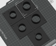
I'm going to print some testers to measure the distortion at different compression ratios for this driver. I am using long ports for this as the ports in my design are relatively long but different to this

I have a 0.2 nozzle on my printer so this is a 13 h 15m print at 0.14mm layer height haha
I have a 0.2 nozzle on my printer so this is a 13 h 15m print at 0.14mm layer height haha
Attachments
Had a quick look at these and I'm not sure they are readily available near me. I have a big idea that might need a lot of drivers eventually haha. If I can get this working how I wantI no longer have any to test, but I used to use Gento SP99023A in synergy horns with pretty good success. I wonder how their distortion measures? There are a bunch of these still on ebay recently, quite inexpensive.
View attachment 1468511
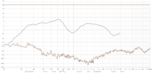
I have done some measurements, these are the overall frequency response of each compression ratio including no front chamber:
All these measurements were done with no filters at 11v (15w)

Distortion for each measurement:


if we ignore below ~1khz for each measurent then we get:
No front: 0.26%
4: 8.8%
3.5: 7.3%
3: 6%
2.5: 4.6%
2: 3.4%
I'm not sure with what I was planning I can use a compression ratio as low as 2 as it would mess with the HF.
I think what I have learned is to measure the distortion of drivers at the compression ratio SD to port area you are planning on using before starting complicated CAD on projects haha.
The front chamber size doesn't seem to make much difference to the distortion. My initial distortion measurements were with a very small front chamber, these were with the front chamber being the whole area in front of the cone.
Another interesting thing is the SD to port area compression ratio doesn't seem to affect SPL much so it might be hard to sim
All these measurements were done with no filters at 11v (15w)
Distortion for each measurement:
if we ignore below ~1khz for each measurent then we get:
No front: 0.26%
4: 8.8%
3.5: 7.3%
3: 6%
2.5: 4.6%
2: 3.4%
I'm not sure with what I was planning I can use a compression ratio as low as 2 as it would mess with the HF.
I think what I have learned is to measure the distortion of drivers at the compression ratio SD to port area you are planning on using before starting complicated CAD on projects haha.
The front chamber size doesn't seem to make much difference to the distortion. My initial distortion measurements were with a very small front chamber, these were with the front chamber being the whole area in front of the cone.
Another interesting thing is the SD to port area compression ratio doesn't seem to affect SPL much so it might be hard to sim
Last edited:
Nice test! As visible in the first graph of your post, there is an increase of 18 dB minimum at 1.25 khz. Would be nice to test without compression at the same spl as with compression to compare the distortion.
hello cemetarysounds - i'm also working with the 2FE22 and I was looking at using it as a FAST tweeter in a horn. but now I'm considering using it as a unity midrange, like you are doing.
what is the volume of your printed enclosure, and would you be open to sharing the stl file with me?
as far as distortion goes, from reading Joe D'Appolito's book on measuring speakers - he recommends placing the speaker in a suitable baffle and getting it up off the ground in "free space" outdoors and away from reflective surfaces. otherwise you are measuring LF background noise/reflections in your distortion plots. I can't find my copy of the book so I am going from memory...
- Home
- Loudspeakers
- Multi-Way
- Small Driver for MEH