Hi DIY-guys,
I am new here as an active member, but profited a lot of this nice forum! So I want to feedback some things I learned from the build up of my Aleph 4 monoblocks. Maybe it gives ideas...
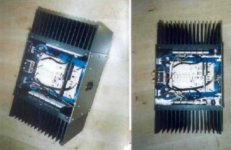
My interest was not to win a design price – but to realize a smallest possible monoblock of an Aleph4 Amp with the easiest way of building a housing. Maybe the attached result not even looks to bad...
Some details:
- two Fischer SK418 heat sinks with 0.25K/W per block plus housing surfaces achieve +30K at 250W dissipation idle power. SK 159 or so also would be fine – highest efficiency caused by 86mm rib-length of the sink.
- the 15mm strong Alu-plate backs of the sinks are a perfect basis to fix four 3mm strong Alu plates around it. Not to nice – but easy doing...
- the packaging is maybe the tightest possible: on the (not visible) 600VA toroidal transformer (65mm high, 135 diameter) the two front caps of 33mF each are mounted. In the middle a DC filter with 2x10mF + 0,1microF Wima found space, also hidden under the PCB.
- the rectifier is build up with four ultrafast diodes, fixed on the small back plate mounted upper sink.
- The two times six FET´s are fixed directly plain to the sinks. The 1,5Ohm power R´s and 220microF gate R´s are soldered directly to the FET´s as also copper rods of 2,5mm² csa. No conductor track for the “signal load currents” to dissipate sound...
- The minimal modified PCB (Thanks to Mark Finnish down-under!) hangs on strings “over all”. Small and cheap horizontal fixed IC-heat sinks with 8,5K/W cool the small FET´s . Welwyn resistors, induction free power R´s, Panasonic electrolyte Caps, KP-caps, mica-cap – nothing not to do the best...
- Additional impulse caps to the big cans (132mF total) were not in that time – now they are fixed on top of the standing rear cans on the bk/wt wires. I found be listening test a “cascade” of 1microFwima MKP, 0,1microF MKP M-Cap Supreme (ultra induction free) and 10nF KP fitting best to my power supply. The wins are really dramatically!
- All 220microF C´s – specially the negative input coupling C – are also bridged by a 10nF KP – test it, you just can win! Solder it e.g. directly under the PCB.
- The sound is much better that I ever have dreamed of...
Warnings – problems I have/had:
- I used “ultra fast”, extreme inductance free transformer, rectifier and cans. This causes a terrible hum! 100 times a second a hart current impulse forced to the poor toroid. It reacts with a bright, hard sound. I test chokes actually to get hold of.
- I bought selected FET´s – but measured “cold”. I got terrible 100mV DC offset on one block, the other just suffers 18mV. Now I will select by myself again
- I did not select the 0,6V-reference voltage power resistors – they have 10% tolerance (but therefor they sound really best!). So one block got 2,3A, the other 2,7A idle current. I corrected it.
- A quite hum is on the speaker – maybe my packaging is to tight and the (shielded) transformer affects the signal electronics, I will never know.
Aleph P gonna come next... Thanks to Nelson Pass to offer us world wide DIY-guys the joy of music with this magic sound! I had an excellent high end amp before (Plinius SA100 Mk3), but the Aleph´s are that much better. The total material costs in spite of the high component quality were “just” 1100Euro.
Best regards from central Europe
Klaus
I am new here as an active member, but profited a lot of this nice forum! So I want to feedback some things I learned from the build up of my Aleph 4 monoblocks. Maybe it gives ideas...
My interest was not to win a design price – but to realize a smallest possible monoblock of an Aleph4 Amp with the easiest way of building a housing. Maybe the attached result not even looks to bad...
Some details:
- two Fischer SK418 heat sinks with 0.25K/W per block plus housing surfaces achieve +30K at 250W dissipation idle power. SK 159 or so also would be fine – highest efficiency caused by 86mm rib-length of the sink.
- the 15mm strong Alu-plate backs of the sinks are a perfect basis to fix four 3mm strong Alu plates around it. Not to nice – but easy doing...
- the packaging is maybe the tightest possible: on the (not visible) 600VA toroidal transformer (65mm high, 135 diameter) the two front caps of 33mF each are mounted. In the middle a DC filter with 2x10mF + 0,1microF Wima found space, also hidden under the PCB.
- the rectifier is build up with four ultrafast diodes, fixed on the small back plate mounted upper sink.
- The two times six FET´s are fixed directly plain to the sinks. The 1,5Ohm power R´s and 220microF gate R´s are soldered directly to the FET´s as also copper rods of 2,5mm² csa. No conductor track for the “signal load currents” to dissipate sound...
- The minimal modified PCB (Thanks to Mark Finnish down-under!) hangs on strings “over all”. Small and cheap horizontal fixed IC-heat sinks with 8,5K/W cool the small FET´s . Welwyn resistors, induction free power R´s, Panasonic electrolyte Caps, KP-caps, mica-cap – nothing not to do the best...
- Additional impulse caps to the big cans (132mF total) were not in that time – now they are fixed on top of the standing rear cans on the bk/wt wires. I found be listening test a “cascade” of 1microFwima MKP, 0,1microF MKP M-Cap Supreme (ultra induction free) and 10nF KP fitting best to my power supply. The wins are really dramatically!
- All 220microF C´s – specially the negative input coupling C – are also bridged by a 10nF KP – test it, you just can win! Solder it e.g. directly under the PCB.
- The sound is much better that I ever have dreamed of...
Warnings – problems I have/had:
- I used “ultra fast”, extreme inductance free transformer, rectifier and cans. This causes a terrible hum! 100 times a second a hart current impulse forced to the poor toroid. It reacts with a bright, hard sound. I test chokes actually to get hold of.
- I bought selected FET´s – but measured “cold”. I got terrible 100mV DC offset on one block, the other just suffers 18mV. Now I will select by myself again
- I did not select the 0,6V-reference voltage power resistors – they have 10% tolerance (but therefor they sound really best!). So one block got 2,3A, the other 2,7A idle current. I corrected it.
- A quite hum is on the speaker – maybe my packaging is to tight and the (shielded) transformer affects the signal electronics, I will never know.
Aleph P gonna come next... Thanks to Nelson Pass to offer us world wide DIY-guys the joy of music with this magic sound! I had an excellent high end amp before (Plinius SA100 Mk3), but the Aleph´s are that much better. The total material costs in spite of the high component quality were “just” 1100Euro.
Best regards from central Europe
Klaus
Attachments
Good job on the compact layout.
How did you fix the problem with the 100hz hum? Did you locate the source?
--
Brian
brian.bell@georgiatech-metz.fr
How did you fix the problem with the 100hz hum? Did you locate the source?
--
Brian
brian.bell@georgiatech-metz.fr
hum elemination
Hi Brian,
I still work on it. First I finally have to look at the source of the hum again with an oscilloscope. I am quite shure I will find those hard ripples when the caps are forcing reload. Then I will try to fix it with two 10mH chokes in a Pi-network. Hopefully that will work...
I will feedback.
Klaus
Hi Klaus,
NIce amp! I just finished my Aleph5. I´ve use a Pi filter with a rel. small choke (1.8mH/0,38R) wich reduces ripple to below 10mV at 2.8A bias. You can only hear some hum if you put your ear against the speaker and that is without a complete case (no sides and top) and with a "flying" earth (not connected in any way to the case).
I think 10mH could be a bit too much.
How did you equal the bias for both channels?
william
choke dimensioning?
Hi William,
thanks for your reply (referring to the privat mail I send you via this forum?)!
How did you find the value for your choke, by simulation with the Software you mentioned?
10mH is to high, I agree. I will decrease stepwise. The choke is created by 30 windings around a ferrit ring, so it can easily be changed. The resistance is less than 50mOhms.
I equaled the bias by finding a more exact resistor with 1,5Ohms. At this resistor now 0,58Volts are dropping. The first, "wrong" (bad toleranced) resistor had just 1,35Ohms - so the current for 0,58V was to high. Over all I got the 2,7Amps. On the other block I contacted a R with 1,55Ohms - causing a little to low current.
regards
Klaus
klaus,
before you spend money on the chokes try to take a hard look at the grounding (especially the input grounds and the PS caps) and at the location of the power transformer. IMHO it's a combination of messed up grounding and layout that is going to be tricky to solve and for which chokes will do absolutely nothing.
From looking at the pics I can see some potential layout shortcomings. For instance, 2 caps are standing up and 2 are laying down that has probably forced you to run long ground connections between them with slightly asymmetric length and orientations and that could give you problems right off the bat.
To test for transformer hum remove the transformer from the box and see what happens or disconnect the input coax from the rca panel and move the open input coax around in the box if you hear the hum varying you got a problem.
I agree with the above. It's rarely the power supply that produces the hum, it's usually improper grounding. Happen to me at least once. After I changed the grounds everything was quiet. None of commercial Alephs using coils, yet they don't hum (some say they sing).😉
Thanks for your hints, I have to explain some more details.
The grounding is totally symmetrically with one “central ground point”. The copper rod lengths to all cans are equal, they form an “H”. The center is the middle of this H, where all ground wires are soldered at. So the theoretical optimum is achieved, theory...
I think my Aleph4 hum – mechanical from the inside of the transformer and audible from the speakers - has nothing to do with the grounding, when I totally disconnect the audio signal input from the PCB it stays exactly the same. I think the audible hum from the speakers is created by the ripples in the PSU and the still to high DC-offset. It is quite silent. But the mechanical hum of the Transformer is the problem. It seams to be a poor mechanical reaction of the shielding metals of the transformer to the current ripples. It is filled with resin, so also theoretically the best quality...
I have no more idea beneath the choke – someone does?
Hello Klaus,
what you could do is reduce the bias (by half or so) and listen if the mechanical / electrical hum is reduced. If so you must reduce the maximum ripple current into the caps (small resistor)
How big is the ripple voltage anyway?
william
what you could do is reduce the bias (by half or so) and listen if the mechanical / electrical hum is reduced. If so you must reduce the maximum ripple current into the caps (small resistor)
How big is the ripple voltage anyway?
william
Small Aleph 4 power block
Klause,
I has similar problems with my stereo Aleph 5 (common supply).
I think I have solved this issue with careful earth bus for the filter bank.
I parrelled 2 rows of (4) x 15,000 uf 63 volt capacitors with snap in luggs using a PCB with 50mm x 170mm earth pad and then laminiated some copper foil to further reduce any potential DCR.
All the capacitors are as close as they can be and the earth for centre tap is in the centre. At each end of the Pcb are the earth points for each channel..... I don't use the centre position for the board earths(or speaker earth) as this is where all the high charging current meet.
I also use a seperate bridge recitifier for each channel which makes quite a difference to the subjective performance. The amp sounds more transparent and dynamic.
Using other means of joining the capacitors, wire links ect resulted in problems with hum and buzz.
Hum is virtually inaudible and only faint high frequency buzz with my hear right near the tweeter (actually a JBL studio monitor 2344A bi radial horn rated at 96dba).
Hope this helps.
regards
macka
If you uncertain if its the ripple from PS causing hum, why don't you run just one channel from the whole supply? If it still hums, it must be the grounding then.
- Status
- Not open for further replies.
- Home
- Amplifiers
- Pass Labs
- Small Aleph 4 power block...