Sloan in his power amp construction maual asserted that cross-over distortion will decrease with output level. More explicitly, he experimented with a circuitry (Figure 7.7a) which has zero Vbias. Sloan fed the circuitry with 1v RMS and 4v RMS signals and concluded that THD increased dramatically when the output was increased from 1v to 4v RMS (page 224-228).
It never made much sense to me. so I decided to give it a run in my spice model.
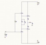
I simulated the following, which is identical to Sloan's except transistor choices (I didn't have MJ15003/4).
here is the answer:
10Khz sinus signal, THD@Input: 82% @1v, 17%@4v, 7%@10vRMS.
1Khz sinus signal, THD@Input: 95% @1v, 18%@4v, 7%@10vRMS.
Not to bore you but the frequency argument in his book doesn't seem to be supported by the simulation as well.
What's your take?
It never made much sense to me. so I decided to give it a run in my spice model.
I simulated the following, which is identical to Sloan's except transistor choices (I didn't have MJ15003/4).
here is the answer:
10Khz sinus signal, THD@Input: 82% @1v, 17%@4v, 7%@10vRMS.
1Khz sinus signal, THD@Input: 95% @1v, 18%@4v, 7%@10vRMS.
Not to bore you but the frequency argument in his book doesn't seem to be supported by the simulation as well.
What's your take?
Attachments
millwood,
Check out the following quote from page 225:
"The important principle involved in these two tests is that the frequency of crossover artifacts increases with an associated increase in signal amplitude. Note that this principle has nothing to do with the level of crossover distortion - only the frequency components associated with it."
I think what he's trying to say in these pages is this. He's trying to make an argument as to why the distortion of the closed loop amplifier continues to decrease as the signal level decreases. He says that as the signal level increases, the distortion spectrum of the open loop amplifier contains a greater proportion of higher-order harmonics. Stated another way, as the signal level decreases, the distortion spectrum of the open loop amplifier contains a lesser proportion of higher-order harmonics. When the loop is closed, the lower order harmonics are easier for the feedback to clean up, since the amount of feedback gets higher as you go down in frequency. The distortion reduction of a given harmonic depends on the amount of feedback at that harmonic (not the amount of feedback at the fundamental), so higher-order harmonics tend to be more difficult for the feedback to clean up.
That's my interpretation anyway.
I decided to take a look at Self on this topic. According to his analysis (which appears to be based on a real amp and not a SIM), what Slone writes is true but isn't a full expanation. Per Self, as amplitude falls so does harmonic distortion in **Absolute Value**, but it does NOT fall AS FAST as signal amplitude hence the **PerCentage** value rises To me this is a lot more plausible as explanations go. Also Self used a optimally biased OPS which seems to be a more valid experiment. (Who cares what the experimental results are if the bias is majorly buggered?) Self also notes that in his experiment the deterioration of THD is actually all that bad anyway.
One thing that bugs me a little about Slones, selfs and Millwoods experiments, is: Are were really looking at just crossover distortion or does switching get in there two? And how does one separate them. I need to re-read the Self essy an switching distortion to see what that says.
BTW, Slone wote another book after this one on audophile projects which included amps. It is fairly appearent that his ideas on amps evolved and may still be evolving. A 2nd addition to the amplifier book in a couple of years that reflected his current thinking and understanding might be interesting.
sam9 said:(...)Are were really looking at just crossover distortion or does switching get in there two? And how does one separate them. I need to re-read the Self essy an switching distortion to see what that says.(...)
I think you'll find that the switchoff distortion issue is dealt with by the 1 uF capacitor in parallel with the bias resistor of the driver transistor. This provides a low impedance path at high frequencies for the opposite polarity driver transistor to remove the stored base charge from the output transistor that it's trying to turn off.

on page 144, Sloan wrote: "the absolute level of crossover distortion decreases as the output signal level is decreased, but not in a proportional manner. ... the end result is only a slight increase in THD as the output level is drastically reduced".
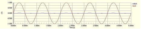
The simulation had pretty much invalidated the last sentence so let's focus on the first one. Since Sloan is talking about the absolute level of distortion, I ran the same circuitry through, again, 1v, 4v and 10v signals. and here it is for the 1v signal. Notice that there is almost nothing on the output - makes sense since the no-conjugate voltage for the driver/output devices are about 1.5v.
The simulation had pretty much invalidated the last sentence so let's focus on the first one. Since Sloan is talking about the absolute level of distortion, I ran the same circuitry through, again, 1v, 4v and 10v signals. and here it is for the 1v signal. Notice that there is almost nothing on the output - makes sense since the no-conjugate voltage for the driver/output devices are about 1.5v.
Attachments
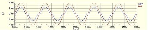
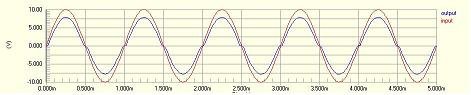
here is the 10v signal. the distortion is about 2.0v. after taking account the voltage drop off the resistor (about 0.22v at peak), the distortion over the device is 1.78v.
so it seems to me that the magnitude of the distortion is pretty much the same: around 1.5v. and in relative terms, distortion goes UP as signal goes down - very intuitive.
There is also no moderation of "sloping" in the non-conjugate areas, as Sloan had indicated on page 225.
Not to mention his assertion, on page 227, that THD increases "dramatically" when signal goes from 1v to 4v.
As to Andy's suggestion that Sloan may be looking at a closed-loop experiment, I doubt that since the whole section is based on the circuitry posted here before and that is certainly an open loop circuitry.
Hopefully, Sloan changes his idea on this as his assertions here don't seem to be true.
I also had a TV that suffered cross-over distortion. At lower level, the sound was very difficult to hear and understand than it is at higher level, consistent with the experiment here but inconsistnt with Sloan's assertions.
The cross-over distortion, unfortunately, even if not "seen" still residues and it is nothing good for listening impression. You should at least set up optimal quiescent current. Please have a look at: www.angelfire.com/ab3/mjramp/index.html
PMA, the purpose of this experiment is to see how cross-over distortion varies with signal magnitude.
As such, setting up optimal bias will totally defeat the purpose. That is why the Vbias is explicitly set to zero.
As such, setting up optimal bias will totally defeat the purpose. That is why the Vbias is explicitly set to zero.
millwood,
OK, then let me share the result of many times repeated experience: the cross-over distortion effect is worse for low-level and high frequency signals than for high-level and low frequency signals. It can be easily heard, if you build a sample of such amplifier. And it can be easily seen on oscilloscope screen.
OK, then let me share the result of many times repeated experience: the cross-over distortion effect is worse for low-level and high frequency signals than for high-level and low frequency signals. It can be easily heard, if you build a sample of such amplifier. And it can be easily seen on oscilloscope screen.
PMA said:millwood,
OK, then let me share the result of many times repeated experience: the cross-over distortion effect is worse for low-level and high frequency signals than for high-level and low frequency signals.
Sloan said the opposite and this experiment is to try to understand the basis for his reasoning.
The last point, and then I promise not to bore anymore. The level where cross-over distortion starts depends on quiescent current value. Highly biased AB design will have no crossover distortion when both output devices conduct (low levels of signal), as it works in class A for low level signals. Low biased or pure class B (dVbe=0) will highly distort for low level signals.
millwood said:here is the 10v signal. the distortion is about 2.0v. after taking account the voltage drop off the resistor (about 0.22v at peak), the distortion over the device is 1.78v.
sorry, the image should have been attached.
Attachments
This fellow Renardson, is amazing! He re-invents all of audio circuitry, and then says that high power is not needed in the home. Much of what he says is not real. Sorry.
🙂. I do not want to argue. I gave that link just because of the oscillograms showing residuals of cross-over distortion at different quiescent currents. Douglas Self shows the similar ones and I believe that evyrybody of us who have built some amps have seen similar phenomena in practice.
john curl said:This fellow Renardson, is amazing! He re-invents all of audio circuitry, and then says that high power is not needed in the home.
He does not have any chance than to say that, as those 1R resistors in his cross-over distortion eliminating design do not allow him to reach higher power ... 😉
it is quite interesting of a concept. It essentially used the bottom half to replicate the (distorted) signal that the top half would have generated in a standard design and subtract (actually add) it back to cancel the distortion.
the pressumption then is that the two halves will have to distort the original signal in exactly the same fashion. That can be a tough proposition to sell in reality.
the pressumption then is that the two halves will have to distort the original signal in exactly the same fashion. That can be a tough proposition to sell in reality.
- Status
- Not open for further replies.
- Home
- Amplifiers
- Solid State
- Sloan: cross-over distortion vs. input voltage