Well I for one look forward to an integrated design with surface mount devices. Not sure I would need that level of amp protection inside a self powered speaker but J W 's design does look nice in his last configuration.
When I solder , I shake a little ..... I concentrate harder - I can still make a
professional junction. It just takes longer.
I am going to choose at least 2 of the best IPS's and make a integrated
OPS/IPS/protection PCB. Hopefully JW will help a bit (with the SMD).
OS
I'm in! I just converted Valery's latest monster into an SMT integrated design, and cured an open circuit 50/60hZ buzz in the process.
Well I for one look forward to an integrated design with surface mount devices. Not sure I would need that level of amp protection inside a self powered speaker but J W 's design does look nice in his last configuration.
Have you got your available space figured out? I'm getting better at compacting amplifiers.
SMPS and class D reminds me of Red Fox's line, "if you ugly with ugly..."😀
JW, the board size can be fairly large as long as I keep the power supply external. At the same time I have to integrate the dsp/dac and a usb input and wifi chip. So a lot to integrate on one large board. I could do this as two separate boards with the amps separated from the digital side of things. I need two amps, one with an output of about 100 watts and the second with only 10 to 20 watts max. I can make my speakers 8 or 4 ohms so that isn't a problem. I think the heatsink is large enough to handle this amount of power.
New IPS Inspired by Samuel Groner
Ostripper,
Will you be working up a PCB layout for this latest IPS?
Ostripper,
Will you be working up a PCB layout for this latest IPS?
Hi OS and all
TPA3251D looks to be an improvement. i have used tpa3100d2(my design), tpa3118(weiner).
Probably will try out the gmarsh tpa3251 version when it comes available. he does a good job,
tpa3100, tpa3118 do not stand up to a good class AB amp imo, that is if you are particular about your sound. they work great in low power portable applications when you leave it on forever.
Nope , the SG-1 transimpedance stage (the folded cascode VAS) is not dependent
on any mismatch from the input pair (unlike a typical blameless).
Edit - the current mirror in the second stage also negates LTP mismatches.
A more detailed explanation is right after fig. 5 in the article - A new audio amplifier topology with push-pull transimpedance stage - Part 1: Introduction | EE Times
I'm getting <3mv with just a standard 220uf DC blocking cap. I did include
the 500R offset trimmer (like in the wolverine) ... just in case.
OS
Last edited:
Ostripper,
Will you be working up a PCB layout for this latest IPS?
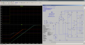
Yes , the simulation has passed all my usual tests (abuses).
THD - stays 12-15ppm 20K from .5 - 2+ volt input - 4-8R load.
Currents - input pair from 1-3ma has no effect on THD , amp
should be very thermally stable because input pair and second stage
is "isolated" from the final stage (transimpedance).
Very wide stable compensation range.
I even swapped out the 992/1845's for 3503/1381's in the
trans-impedance stage - almost no change in THD or currents.
This design is not "picky" about it's silicon.
- 35V to 80V rails ...... no change at all.
This IPS "self balances" itself.
It is ready for "prime time".
OS

...
Maybe I'm wrong but I measured a slewrate of about 42V/µs.
...
No answer so far ......
Has someone checked the 42V/µs slew?
...
Either my simulations are completely wrong or the slewrate is about 40V/µs.
A "SlowSlew" in the "SlewMaster" thread? 😕
BR, Toni
Attachments
"listening impression"
I have not built it yet ??
It should be as excellent as all the others.
It has the BEST PSRR of them all. THD is ultra low , it is fast ....
(below ) it is finalized.
Hope Mr. Groner won't mind if we actually listen to it (in slewmaster form).😀
.ASC (final) is posted. Can't make it fail on the simulator - unless I go to
nearly no Q1/2 degeneration and <22pF for C5.
OS
I have a question that regarding the source / emitter degeneration resistor.
I sometimes feel to remove these but as said the amp will end up oscillating but what if we use higher compensation cap to stop the oscillation?
Agreed the fact that using source degen resistor will balance the current to an extent.
In that case why cant we use advanced wilson current mirror which controls almost exact current to the input transistors / jfets?
Yes, Groner's circuit has a low slewrate but, that doesn't impact performance to signals that we actually tend to listen to.
The folded cascodes need to have high bias to increase slew rate.
The folded cascodes need to have high bias to increase slew rate.
Last edited:
I have a question that regarding the source / emitter degeneration resistor.
I sometimes feel to remove these but as said the amp will end up oscillating but what if we use higher compensation cap to stop the oscillation?
Agreed the fact that using source degen resistor will balance the current to an extent.
In that case why cant we use advanced wilson current mirror which controls almost exact current to the input transistors / jfets?
Degenerating the LTP and lowering compensation improves slew rate. Also compensation can't be too small otherwise the excessive phase of the individual stages dominates and causes oscillation.\
OS, is the diamond buffer thermally stable?
No answer so far ...
Either my simulations are completely wrong or the slewrate is about 40V/µs.
A "SlowSlew" in the "SlewMaster" thread? 😕
BR, Toni
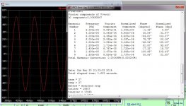
Yes , you are right on.
43v/us with 68p (c5) and @75 with a 39p for C5.
But read Groners article , his TIS (folded transimpedance stage) is 225v/us.
Now , this "tit for tat" "speed fetish" needs to be clarified.
Any of these amps are getting fed by soundcards , various pre-amps. The
TI sheet for my ASUS xonar ne5532 is 9V/us .
The fastest Kypton-ND or CFA-X is >200V/s front to back , fed from
my ASUS (with the 9v/us) .... will this matter ??
The real POWER of this Groner design is having a asymetric primary I-V stage
buffered by a symmetric TIS .... the real Electrocompaniet ampliwire
uses this trick to cancel BOTH even and odd THD plus get that PSRR
down.
PS - I have also designed blameless's (wolverines) all "slow" VFA's .....
they are <60V/us ..... but they sound great - SO WHAT ??
OS
Degenerating the LTP and lowering compensation improves slew rate. Also compensation can't be too small otherwise the excessive phase of the individual stages dominates and causes oscillation.\
OS, is the diamond buffer thermally stable?
SG-1 TIS has no diamond buffer ? Groner never referred to it as such ?
PS - thermal sims show a little positive tempco ... but actually swapping
device models , current stays real consistent. (I don't trust LT's thermal
modelling) Below is the swap - just .05ma current change with Q11/14
swapped with to-126 models
OS
Attachments

Nevermind, not a diamond buffer, but a diamond TIS (or whatever Groner calls it). It should be stable as long as Q11/14 are coupled to Q9/12.
I have made a lot of improvements to my model library so far - better models for the 992/1845 including quasi-saturation and several others. Attached.
I have made a lot of improvements to my model library so far - better models for the 992/1845 including quasi-saturation and several others. Attached.
Attachments
Yes , you are right on.
43v/us with 68p (c5) and @75 with a 39p for C5.
...
Fine that you could verify this.
I personally have no problem, if the slew rate is not astronomically high as long as the amplifier can perfectly follow the music signal and has enough NFB to hold distortions as low as possible. You know that I'm not a CFA fan.
BTW: The latest SG-1 simulation showed those lower slewrates but also lower NFB at 20kHz (If I correctly remember: openloop gain 34db versus > 60dB of a TMC blameless). Maybe you can get more headroom out of it? 😉
Have fun, Toni
Degenerating the LTP and lowering compensation improves slew rate.
Another advantage appears to be that heavy IPS degeneration makes an amp (at least a folded cascode - not simulated others recently) more tolerant of reactive loads. The reduction of stability margins seems smaller when using a reactive load vs resistive. But at the expensive of a small increase in THD consistent with the reduction in LG. A penalty I'm willing to take these days....
Have others found this?
Paul
yes , little gain margin at 20K (2-4db) ..... BUT still <10ppm (20k/60v p-p) ?BTW: The latest SG-1 simulation showed those lower slewrates but also lower NFB at 20kHz (If I correctly remember: openloop gain 34db versus > 60dB of a TMC blameless). Maybe you can get more headroom out of it?
Perhaps the TIS of the SG-1 is more linear than a blameless - does not
need as much NFB ??
2 ways to skin a cat.
PS - A higher beta input pair with minimal degeneration could squeeze
several more db of 20K gain margin - but , do we really need it ?
15ppm is ok for 100v p-p 20k /4R with just 5db gain margin 20k ? (below).
This is a "belief" of some amp designers (make linear - use minimal NFB)
Seems to work here .... larger load - voltage swing does not seem to increase
THD at all -TIS is retaining linearity.
OS
Attachments
- Home
- Amplifiers
- Solid State
- Slewmaster - CFA vs. VFA "Rumble"