All the other Slew IPS were plug and play. This one seems to be a real challenge. Is it worth it? I have built this one twice but not powered it up due to the issues Thimios keeps having.
Half the fun is the battle.All the other Slew IPS were plug and play. This one seems to be a real challenge. Is it worth it? I have built this one twice but not powered it up due to the issues Thimios keeps having.
Terry,
Perhaps you would find that with different final components on your boards vs what Thimios has on his that yours may not have this oscillation? If that is the case it would be interesting to find out what is causing the differences. Worth a try it seems.
Perhaps you would find that with different final components on your boards vs what Thimios has on his that yours may not have this oscillation? If that is the case it would be interesting to find out what is causing the differences. Worth a try it seems.
I guess I'll have to build it.
I made no overstatement that this could be a RF amp. 😱
What is different on this one ... is that these issues are not evident
on LT 😕 . Neither the thermal or this unstabilty. Simulates like a champ.
OS
I made no overstatement that this could be a RF amp. 😱
What is different on this one ... is that these issues are not evident
on LT 😕 . Neither the thermal or this unstabilty. Simulates like a champ.
OS
Terry,
Perhaps you would find that with different final components on your boards vs what Thimios has on his that yours may not have this oscillation? If that is the case it would be interesting to find out what is causing the differences. Worth a try it seems.
Likely the cause is the fact that it's so fast. Compensation needs to be perfect.
I guess I'll have to build it.
I made no overstatement that this could be a RF amp. 😱
What is different on this one ... is that these issues are not evident
on LT 😕 . Neither the thermal or this unstabilty. Simulates like a champ.
OS
Yes but you do not simulate wire inductances and the voltage generator for the supply is a perfect source....
What do you expect? Not only you but all.
Sent from my iPhone using Tapatalk
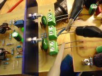
I can also not see any bypass caps on your pcb to GND.!? So i suspect a new layout with bypass caps would help a lot. First run i would avoid self made caps, Special "audio caps" and so on... Use a GND plane as well. Short Wires.... etc.
C9/10 near the V+/V- to ground , same as all the other IPS's. Plus local
decoupling at the input diamond C5/8 ....
thimios might try removing them (another added "suggestion").
- the most basic 2 diamond IPS configuration.
OS
I have check this again and again.
Oscillation is present with this IPS only. I already tried with other IPS and there isn't any oscillation.
When power is off oscillation is gone.
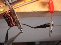
If not this heavy oscillation should rise if you get closer to the PCB.
It is true,i have checked this also.When coil is near VAS transistors i see the max amplitude
Perfect... God way to use it as a sniffer probe., but i does not have to be the VAS stage. But to help it a bit .... If you have any low impedance capacitor like Panasonic FC or simelar. Then connect it from VAS supply to GND directly. Maybe isolate front stage from VAS stage using a RC lowpass on the supply line. That should be possible on your layout as well.
Yes but you do not simulate wire inductances and the voltage generator for the supply is a perfect source....
What do you expect? Not only you but all.
Sent from my iPhone using Tapatalk
But If I build it - I can go through a dozen changes in 5 minutes. A much shorter
feedback loop (from me to me 😀 ) , then from Greece to me to Greece . See ?
I have 2 more IPS's that I know will work - on the layout block now ,
(bootstrap IPS and "symetri").
OS
Strange thing is that oscillation isn't visible when amplifier tested with square wave and zobel isn't warm😕
Could you show a scope output at different level and no input signal as well. Where we clearly Can see it?
Sent from my iPhone using Tapatalk
Sent from my iPhone using Tapatalk
I haven't special parts here ,no KSA1381/KSC3503 same hfe range😀😀😀Perfect... God way to use it as a sniffer probe., but i does not have to be the VAS stage. But to help it a bit .... If you have any low impedance capacitor like Panasonic FC or simelar. Then connect it from VAS supply to GND directly. Maybe isolate front stage from VAS stage using a RC lowpass on the supply line. That should be possible on your layout as well.
Sorry did you mean a scope at speaker out without any inp.signal or a scope picked by the coil?Could you show a scope output at different level and no input signal as well. Where we clearly Can see it?
Sent from my iPhone using Tapatalk
Keep in mind that this oscillation is without any inp. signal.
Last edited:
Sorry did you mean a scope at speaker out without any inp.signal or a scope picked by the coil?
Keep in mind that this oscillation is without any inp. signal.
I would like you to measure at the output with probe In 1:1
Also do the same at the VAS stage output.
Sent from my iPhone using Tapatalk
Ok, tomorrow morning i will measure this with and without load.I would like you to measure at the output with probe In 1:1
Also do the same at the VAS stage output.
Sent from my iPhone using Tapatalk
Not neglecting my "duties".
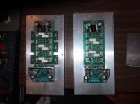
Have everything for the 2 amps below.
Left one is the Sub amp competed (milled). Powerful 3 pair MT-200 400W unit ,
Neal Peart drums will sing well (Rush drummer).
The right one will be the "sacrificial" amp. 😀
Have 10 pair E-waste Sanken mt-100's to (burn up). I won't use my good
outputs. Add a E-waste PC fan ... all set to burn on my 200W 5R load .
Better for the "cause" - I can "burn-in" any IPS (under observation).
I now appreciate the builders (thimios + still4given) , hard work. 😱
PS - milling with a painful toothache is even harder ... yikes.
OS
Attachments
Have everything for the 2 amps below.
Left one is the Sub amp competed (milled). Powerful 3 pair MT-200 400W unit ,
Neal Peart drums will sing well (Rush drummer).
The right one will be the "sacrificial" amp. 😀
Have 10 pair E-waste Sanken mt-100's to (burn up). I won't use my good
outputs. Add a E-waste PC fan ... all set to burn on my 200W 5R load .
Better for the "cause" - I can "burn-in" any IPS (under observation).
I now appreciate the builders (thimios + still4given) , hard work. 😱
PS - milling with a painful toothache is even harder ... yikes.
OS
It's nice to see things coming together. When does the input factory open for business?

It's nice to see things coming together. When does the input factory open for business?
February , I'll have toner then , too.
Sir Apex said I could "IPS" his SR/AX lineup , as well. 🙂
OS
infidel ver.2
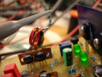
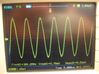
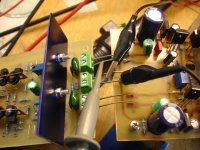
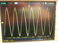
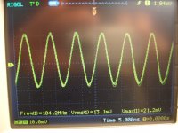
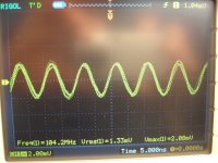
Here are new measurements with shorted inp.
1)A resistor in series with the pickup coil
2)oscillation by the coil collected
3)Probe at VAS out -
4)oscillation at Vas out -
5)probe at VAS out +
6)oscillation at VAS out +
7)probe at amplifier out
8)oscillation at amplifier out.
Here are new measurements with shorted inp.
1)A resistor in series with the pickup coil
2)oscillation by the coil collected
3)Probe at VAS out -
4)oscillation at Vas out -
5)probe at VAS out +
6)oscillation at VAS out +
7)probe at amplifier out
8)oscillation at amplifier out.
Attachments
Last edited:
104,2 MHz, that is seriously High frequency oscillation, are your compensation npo..?
Some rail R/C may also be useful, like 10 ohm and 47uf right at the input stage
I believe the this is due to cabeling and absence of a ground plane, the infidel is so fast the RF PCB skill are needed.
Some rail R/C may also be useful, like 10 ohm and 47uf right at the input stage
I believe the this is due to cabeling and absence of a ground plane, the infidel is so fast the RF PCB skill are needed.
- Home
- Amplifiers
- Solid State
- Slewmaster - CFA vs. VFA "Rumble"