Ok i will try this soon.I'm not so fond of the Cpb 1-2 capacitors, think they need to go. And then the compensation C-7,C-8 may need some increase to maybe 47-68 pF
What does Ostripper have to say to this zobel lamp..??
" Still jet lagged from new years grub"
No,i'm busy housing the sx amplifier .🙂
I have many amplifiers roofless🙁
Last edited:
I think OS needs some time to get his test amp built. 😀
Yeah , time .... kid going to college $$$$ (ripoff fees) ... mini vacation (another ripoff) 🙁 .
But , I'm getting what's untested - tested on what does work (below).
Tester PS , Sub PS , and (empty main PS PCB). Jeff's PCB's all work at 76Vdc.
4.7K/2w bleeders get hot ... but are OK at 45-60V (sub and tester voltage).
Don't need bleeders on the main amp - good !
Valery's protection board soft-start works good with 50Kuf at full rails.
Ran the "spook's" with 2 pair OP on those PS's - LOUD/ clear/silent !!
At least every amp , PS , accessory ... works perfect with no bugs.
(no major "magic smoke" or BOOM , yet. 😀
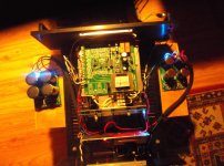
Sub and tester amp is getting machined now. 😎
edit-Thimios can also raise R9 -15 on the infidel 2 to 47-56R (lower gain Re).
That's what did work on Infidel V1.
OS
Attachments
Ok i will try this soon.
" Still jet lagged from new years grub"
No,i'm busy housing the sx amplifier .🙂
I have many amplifiers roofless🙁
I'm "roofing" 4 big ones now - hard work .
I'll just try harder , will not "roof" any wrong !
OS
I tried all suggestions .R9,15=47R, 0.22uf putting again ,increasing compensation to 47pf but i can't see big difference.This IPS is unstable especially in low out levels
I tried all suggestions .R9,15=47R, 0.22uf putting again ,increasing compensation to 47pf but i can't see big difference.This IPS is unstable especially in low out levels
A resistor needs to go between R10/14 and R11/15.
(both 10/14 and 11/15 need to be individually bridged) 10/14 is already bridged ...Then add a 22R between the bridges .
I did this on advise. (should of kept the 22R - V1) While I am open
to suggestions from others , sometimes they do not work ..... unfortunately.
OS
Last edited:
Hi OS this IPS is strange.Cut the trace between R14/15 and R10/11. Add a 22R there (bridge the cut trace).
I did this on advise. (should of kept the 22R - V1) While I am open
to suggestions from others , sometimes they do not work ..... unfortunately.
OS
I can't understand some things.
Why VAS current increase when signal applied?
Is this because oscillation?
When no signal aplied the VAS current is about 5mA.(0.64V on R22).
When signal is present the current increases a little.(0.86V on R22).
This amplifier is unstable periodically.When scope this, you can see fast rips but zobel is cold even at 100 Khz square wave!
I will post some photos tomorrow.
Please OS, tell me which modifications you want to keep from the original schematic.
Last edited:
Hi OS this IPS is strange.
I can't understand some things.
Why VAS current increase when signal applied?
Is this because oscillation?
When no signal aplied the VAS current is about 5mA.(0.64V on R22).
When signal is present the current increases a little.(0.86V on R22).
This amplifier is unstable periodically.When scope this, you can see fast rips but zobel is cold even at 100 Khz square wave!
I will post some photos tomorrow.
Please OS, tell me which modifications you want to keep from the original schematic.
Full pix of changes (back to V1 "core") below. Add "Rb" , omit the "Cbp 1/2".
PS - undoing the "suggestions" - back to what should (did) work. 😱
OS
Attachments
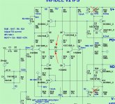
Ok i will try this tomorrow morning.Full pix of changes (back to V1 "core") below. Add "Rb" , omit the "Cbp 1/2".
PS - undoing the "suggestions" - back to what should (did) work. 😱
OS
Here are the results.🙁Ok i will try this tomorrow morning.
Attachments
Looks better, also it makes sense to have some damping between the two diamonds...
I totally agree with the removal of the VAS to rail capacitors and the increase of the normal compensation caps. Hob much did you increase, what is the frequency of the oscillation??
Hope you get the VAS drift under control
I totally agree with the removal of the VAS to rail capacitors and the increase of the normal compensation caps. Hob much did you increase, what is the frequency of the oscillation??
Hope you get the VAS drift under control
Last edited:
Here are the results.🙁
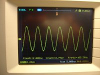
Those are some interesting peaks on the waveforms.
Compensation caps value is 47pfHere are the results.🙁
I will try to explain....
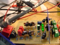
First photo show the scope probe connected to a pickup coil.
Second photo ,click on photo and see on screen 105.3 MHz oscillations!
Last edited:
Compensation caps value is 47pf
I will try to explain....
First photo show the scope probe connected to a pickup coil.
Second photo ,click on photo and see on screen 105.3 MHz oscillations!
So the issue isn't just the extra peaks then, It's the whole waveform.😱
Exactly😱So the issue isn't just the extra peaks then, It's the whole waveform.😱
Is your place any where close to an FM broadcast antenna? Are you able to get the frequency you picked up to change by altering the IPS board, for example, shorting/opening circuit the input to GND, lifting LPF filter, changing bias current?
Just to be sure, add a series resistor to your coil. Lets say 500 - 2K .. If this removes the oscillation, it just might be that you have made a parallel resonance circuit build up by the probe capacitance and the coil. Then it is most likely to be an FM transmitter somewhere by.
If not this heavy oscillation should rise if you get closer to the PCB.
This simulation does not tell you, even after hundreds of hours!!!!!
I can also not see any bypass caps on your pcb to GND.!? So i suspect a new layout with bypass caps would help a lot. First run i would avoid self made caps, Special "audio caps" and so on... Use a GND plane as well. Short Wires.... etc.
Caps should be low esr low esl. And bypass them polypropylen capacitors to get as wide low impedance band as possible.
Sent from my iPhone using Tapatalk
Sent from my iPhone using Tapatalk
Just to be sure, add a series resistor to your coil. Lets say 500 - 2K .. If this removes the oscillation, it just might be that you have made a parallel resonance circuit build up by the probe capacitance and the coil. Then it is most likely to be an FM transmitter somewhere by.
If not this heavy oscillation should rise if you get closer to the PCB.
This simulation does not tell you, even after hundreds of hours!!!!!
I can also not see any bypass caps on your pcb to GND.!? So i suspect a new layout with bypass caps would help a lot. First run i would avoid self made caps, Special "audio caps" and so on... Use a GND plane as well. Short Wires.... etc.
I have check this again and again.
Oscillation is present with this IPS only. I already tried with other IPS and there isn't any oscillation.
When power is off oscillation is gone.
If not this heavy oscillation should rise if you get closer to the PCB.
It is true,i have checked this also.When coil is near VAS transistors i see the max amplitude
Last edited:
- Home
- Amplifiers
- Solid State
- Slewmaster - CFA vs. VFA "Rumble"