well , I can't give you entire electronic course in short , not even counting on fact that I would teach you wrong about almost everything 
believe me - put 1A4 CCS as load ; when you feed SIT-1 circuit with 90Vdc where it is appropriate (on top of resistive load) , it'll behave as bloody 1A4 CCS
or - if you still insist on resistive load in sim , why not opting for 90V/1A4=64.3 Ohms
from where you got 20R there ? .........
edit: nice book : https://dl.dropboxusercontent.com/u/20665608/For DiyAudio.rs/ELECTRONICS_A_Complete_Course.rar
I would be a very lucky fellow if I could steal that much time from you!
In my previous posts I tried to put across that I came upon the 20 R value by inserting the specs for the transformer that came in the amplifier (72 volts @ 4.2A) - and using values for R1 until I got 90 volts output. That corresponded with 20 ohms.
AS always, your advice and patience are immensely appreciated.
PS needless to say I would much prefer the 64 R load to be the correct one. All is simplicity if that is the case!
Attachments
Last edited:
when working in PSUD , with goal of deciding which values one need for custom xformer , it's sorta tricky inputting real xformer data , prior to having it
I mean primary on Rdc of both primary and secondary ..... however , that's also sorta easy , just borrowing Rdc of primary form similarly sized xformer , and getting secondary Rdc as multiply from some known xformer
so , to cut story short - upload your *.psu file (zipped) here and I will see what I can do , to make it easier for you
Those are real ANTEK transformers. I have used the data sheet specs for the standard 300 VA 36 + 36 V and 4.2 A.
For the choke input version I posted before I was using a 500 VA 54 + 54 V and 4.6 A. This is now too large.
I have not measured the resistance of the primary and the secondary of the transformer in the amp but in the past I have found those derived numbers to be fairly close and not affecting the numbers too much.
So, the below looks like it should work just fine. Using the 300 VA 50 + 50 V 3 A transformer from ANTEK and a single LL2733.
To please Eduard there is a little room for a bleeder. Eduard, I love bleeders - I figure they were the first shunt regulator.
Attachments
Last edited:
also try 400mH/3R4 , just from curiosity
Looks good. My mains are around 122 volts so that would easily take this to 90 .
Attachments

Hello,
Mister Zen is absolutely right if you use 20 ohm as a load of course there willbe way to much current.
I did bringthe chokes for my friend Tho in vietnam .He will make the second version of the sit amp .
I told him to make a string of 2,2 or 1,5 ohm power resistors so he can create a perfect load similar to his amp including the bleeder.
Because of the relatively high dcr of the ll2733 it is rather difficult to predict the output with the choke right after the Rectifier!
In the past I did use chokes in solid state class A amps but never in a choke input. Now I have a DDDAC which takes a lot of current and I know with 1A or a bit more you will get a big voltage drop. If I remember well I only got about 13,5 volts at the first cap with a 21 volt ac transformer, a 1A load and a ll2733 mounted as common mode choke input.
I told my friend just to try several topologys .
I think that choke input isthe way to go. Maybe common mode with 2*1,7 ohm will be to much dcr. So maybe put the coils in parallel and have just 100mh instead of 400 mh but just 0,85 dcr. I think 100mh choke input will be better than 400mh in common mode between two caps (CLC)
But with100mh you will need a 4 times bigger bleeder which will give a bigger ripple.
My friend just have to try them all lol
Greetings, eduard
Last edited:
post zip file here , for my pleasure ;
besides feeling pressure in sinus area , I'm also lazy .....
besides feeling pressure in sinus area , I'm also lazy .....
Hello,
You see not a lot of people interested in giving the choke input a serious change.!
Of course you need to buy some chokes and another power transformer but that is all.
So far when I did change a device into choke input it has always been a big improvement.
Greetings, eduard
You see not a lot of people interested in giving the choke input a serious change.!
Of course you need to buy some chokes and another power transformer but that is all.
So far when I did change a device into choke input it has always been a big improvement.
Greetings, eduard
You can also try using the primary of a large power transformer as a choke Oh I know people will start yelling it's not air gaped ect. but I tried it out and it works fine. I didn't see signs of saturation even with short test where I exceeded the primary current rating by 2x that is used a 110v 100 va transformer as a 2 A choke.
Me too 😀You can also try using the primary of a large power transformer as a choke Oh I know people will start yelling it's not air gaped ect. but I tried it out and it works fine. I didn't see signs of saturation even with short test where I exceeded the primary current rating by 2x that is used a 110v 100 va transformer as a 2 A choke.
my autotransformer, the Secondery of toroidal transformer .... sometimes be use as a choke if they not been saturated or get hot.
Hello,
My friend in Vietnam got a pair of LL2733 some time ago. Let us wait untill he starts using them for a choke input power supply! There is not much to explain about choke input power supplies. I mean there are no new theories . It has all been described decades ago.
The things that need to be taken care of:
Calculate the minimum inductance you need to make it work as a true choke input!!!
Take care there is always a bleeder installed to make sure the supply always has to supply some current.
The higher the number of mH the less current you need to bleed.
The Lundahl can be used with the 2 coils in parallel or in series. This will give you 400 mH 3,4 ohm or 100 mH 0,85 ohm. With 400 mH you need less bleeder current but there is the 3,4 ohm. With the same transformer the dc output will be lower.
One should have a transformer with multiple secundaries so one can get the same output voltage with 400 and 100 mH and then just compare by listening.
Of course with a single ended pass design one could use the 400 mH in what Lundahl calles serial connection for improved common mode rejection in their PDF files.
We will have to wait untill somebody really tries choke input for their Pass designs!. So far there is just a German audiophile who did try it.
Let us wait and see for Tho!
greetings, Eduard
I am using the LL2733s as choke input filters on my mono-fied J2 for months now.
They do not warm up at all so I know, now, that I can use a bleeder. I initially left them out for fear I was too close to the limits of the chokes.
Works just fine.
I will eventually install these in the SIT1s along with the requisite higher voltage power transformers.
There is an added refinement to the sound.
I would fear with the coils in series could there be too much resistance for a power amp supply The output is lower. One would have to use an even higher voltage power transformer. I am using a 30+30 volts, to get the same output voltage I would need to use 32+32.
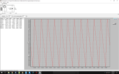
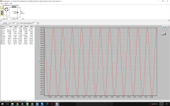
The predicted results from DUNCAN AMPS PS tool show there is a large reduction in ripple from the higher inductance but I was able to get the same reduction with the parallel connection by inserting the same filter Mr. Pass uses, an RC of 0.117R and, in my case, 100m cap. Obviously, an even better result occurs with the series connection and this added filter but that is when I worried that 3.4 ohms might be too much in a power amplifier.
Duncan's tool predicts 543 uV ripple for the series LCRC and 2.16 mV for the parallel connection. The series connection uses the 32+32 transformer. Output voltage for both are with 0.3 volts of each other.
They do not warm up at all so I know, now, that I can use a bleeder. I initially left them out for fear I was too close to the limits of the chokes.
Works just fine.
I will eventually install these in the SIT1s along with the requisite higher voltage power transformers.
There is an added refinement to the sound.
I would fear with the coils in series could there be too much resistance for a power amp supply The output is lower. One would have to use an even higher voltage power transformer. I am using a 30+30 volts, to get the same output voltage I would need to use 32+32.
The predicted results from DUNCAN AMPS PS tool show there is a large reduction in ripple from the higher inductance but I was able to get the same reduction with the parallel connection by inserting the same filter Mr. Pass uses, an RC of 0.117R and, in my case, 100m cap. Obviously, an even better result occurs with the series connection and this added filter but that is when I worried that 3.4 ohms might be too much in a power amplifier.
Duncan's tool predicts 543 uV ripple for the series LCRC and 2.16 mV for the parallel connection. The series connection uses the 32+32 transformer. Output voltage for both are with 0.3 volts of each other.
Hello,
As they say the proof of the pudding is in the eating!
Maybe because the current drawn by the class A design is pretty steady? the extra serie resistance would not be a problem?
Maybe can compensate this by adding extra caps?
I think the most important thing is to have it working as a true choke input.
For extra filtering you could add and extra network of a resistor and a cap.
It seems that using the serie connection with improved common mode rejection could be beneficial.
In all the devices that i use with choke input putting a choke with higher mH was an improvement.
IF it will be better for the SIT we dont know unless someone tries. Maybe it will depend on the speakers and or the frequency range for which the amp will be used.
Greetings, Eduard
IME choke input at near the choke rated current does not work so well with Lundahls. Maybe i've had a lot of duds, dunno, but be prepared for a nicely pitched buzz.
Hello,
I did use several LL2733. There is a German supplier that sells 4 different types each having different mH and current rating. Smaller airgap will give higher mH but lower current rating. NONE of them did make the slightest noise. AND i did try them at maximum current too. Another German supplier states on his website that if the ac across the choke is lower than the one mentioned in the Lundahl PDF the current can be considerably higher!
Greetings, Eduard
I tried to use my LL2733 for choke input. I wiring as the third schematic of LL2733 datasheet with a big resistor create a current close to 1A load and 100000uF capacitance. The output voltage is close to 26VDC with 30VAC and I think that is the good flat DC and I think it's not necessary to use active regulator.Hello,
My friend in Vietnam got a pair of LL2733 some time ago. Let us wait untill he starts using them for a choke input power supply! There is not much to explain about choke input power supplies. I mean there are no new theories . It has all been described decades ago.
The things that need to be taken care of:
Calculate the minimum inductance you need to make it work as a true choke input!!!
Take care there is always a bleeder installed to make sure the supply always has to supply some current.
The higher the number of mH the less current you need to bleed.
The Lundahl can be used with the 2 coils in parallel or in series. This will give you 400 mH 3,4 ohm or 100 mH 0,85 ohm. With 400 mH you need less bleeder current but there is the 3,4 ohm. With the same transformer the dc output will be lower.
One should have a transformer with multiple secundaries so one can get the same output voltage with 400 and 100 mH and then just compare by listening.
Of course with a single ended pass design one could use the 400 mH in what Lundahl calles serial connection for improved common mode rejection in their PDF files.
We will have to wait untill somebody really tries choke input for their Pass designs!. So far there is just a German audiophile who did try it.
Let us wait and see for Tho!
greetings, Eduard
eduard,
I am using an LCRC filter. Last cap is 100mF.
analog_sa
The chokes do not even begin to get warm so I feel confident they are not under any stress at all. I would not be surprised if one supply was powering both channels it might not have worked so well.
I am using an LCRC filter. Last cap is 100mF.
analog_sa
The chokes do not even begin to get warm so I feel confident they are not under any stress at all. I would not be surprised if one supply was powering both channels it might not have worked so well.
Last weekend I changed over one of the SIT1s to the LCRC supply.
All works well.
I think I am hearing the same effect I heard after doing this to the mono-ized J2s - when comparing to the standard supply amp there is a smoother sound - not one cleansing of details but I imagine that the sound is due to the more sine like ripple using the choke input supply. As I said before about the J2s - there is a burr missing from the sound. Cymbals have a more lifelike shimmer is the most immediate impression.
When both amps are the same again I will be able to make a better assessment.
This is a tight box. To give the stuff a little more room I split the capacitor board in half and stacked the two halves atop each other.
I used an ANTEK 50 + 50 volts transformer. My line voltage is rather high and I was hoping I would have lower resulting B+. It is lower but I wish it was lower, still. I could use a bleeder to bring it down but it would require a resistor with massive power handling to make a real difference. Not going to bother at this time.
After the choke there are a pair of 27,000 uF caps then to a .27R Mills 12W resistor which goes into the original capacitor board.
The thermistors are now on the hot lead and there is a switch to bypass them. I leave them in about 10 seconds and then switch them out. I used three in series to be really safe at turn on.
As always one thinks this is going to give a result that is impossible to realize and that is the case here. But I know I am glad I did it. The improvement is small but worthwhile.
Thought I had plenty of switches so I am having to wait for one to come from MOUSER before proceeding with the other amp.
Embarrassing confession: I went for hours trying to figure out why I was not getting power at the rectifiers. Was about to change out the power transformer when I thought I had best look at my power leads. I am using the POWERCON connectors instead of IEC - they are inline so I do not have the wire sticking out from the amplifier. One of the wires had slipped out of the terminal. I am using 10 gauge wire which is the upper limit of what these can accept. To be sure I soldered the thing in this time. Why do I have to learn these same lessons over and over?
Also learned that all fuses are not made the same. I had some ceramic body 2.5 amp fuses - not audiophile - SCHURTER - and these kept blowing at turn on. This was very distressing. I had tried the supply attached to a 50R load and all was fine but connected to the actual circuit these fuses let go.
Put in the original fuse and all is well.
Last edited:

- Status
- Not open for further replies.
- Home
- Amplifiers
- Pass Labs
- SIT1 Choke Input Power Supply?