I must be determined to hear if this is worth the trouble. I know Mr. Pass has done his best to dissuade me from doing this.
I made a few observations - the SIT1 uses a 72 volts AC power transformer and a single bridge rectifier which is then split into what I measure to be +- 40 volts rails. My AC line is a little high so that number is slightly higher than it should be.
My first idea was to simply use a 100 volts power transformer into the rectifier and then to a LUNDAHL LL2733 choke configured for 100 mH and .875 R.
Using the DUNCAN power supply modeler this says I will be running much more current through the choke than it can handle. I wonder if this was why I was told this was not a good idea since if the LUNDAHLs cannot be used. There is nothing of a similar physical size available.
So I wonder if I use the two 50 volts windings (instead of using them in series) and using two bridge rectifiers and two chokes I can get the current down to just within the choke's limits.
First question is: are both supplies required to deliver the same amount of current? With the extra caps on the plus side I wonder if one side is being asked to deliver more than the negative side - if this is the case that makes the chokes unusable.
If not, and the two supplies are delivering approx equal current it can work. I will have to mount the capacitor board vertically to get the room required.
My question with the sincere hope I will get an answer from the only one who REALLY knows - is am I on the right track? I know I can get this to work if this is all there is to it. If there is a pitfall I cannot see please let me know.
Initially it seemed it would be very simple and now I see it will require much more time than I thought but it is getting cold outside and one must keep themselves busy indoors.
I have this belief (and that is the only way to describe it) that this will make these wonderful amplifiers even more lovely to listen to - not night and day, of course, but when one is straining for nirvana is there any route that should not be taken? And there is the crux - is there more potential for destroying a precious output device than there is a chance of hearing a slightly better amplifier?
Unless there is something I am not aware of I feel confident I can do this without destroying anything but there is so much of which I am unaware.
I will never change these amps so concerns about resale value are not a factor; someone always has to throw that in.
Guidance is needed and greatly appreciated.
Thanks and take care,
There is only 1 supply rail at about 90 volts. The -V you see in the
simplified schematic is about -5V for biasing the Gate of the SIT.
If you want to run the SIT into a choke I suggest a quiet regulated supply
at about +15V and a bias current of 1.4A.
simplified schematic is about -5V for biasing the Gate of the SIT.
If you want to run the SIT into a choke I suggest a quiet regulated supply
at about +15V and a bias current of 1.4A.
Thanks for your time.
Shows how good my analysis is. I found those two points marked D & G and did not bother to look at the polarity of the voltage.
I would like trying a choke but if that is all on one rail no chance of finding a choke that would fit int he thing. Unless you have a suggestion ...
So are you saying all of that "extra" voltage is being bled away by those resistors?
And that the SIT 2 is using a much lower voltage power supply?
I am much more comfortable (and safer) with passive components. A regulator for the amp is well beyond my capabilities. AS if I had to even write that.
THANKS again for your time and trouble.
Hello,
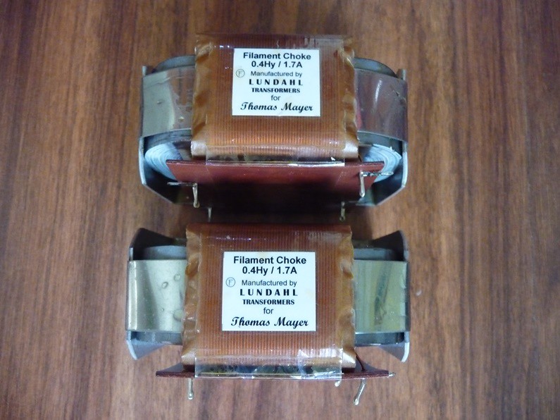
A few days agomy Vietnamese friend Tho got his pair of lundahl ll2733. He will use them in a single ended transistor design by Nelson Pass.
Already did type to much about choke input power supplies for devices with higher currents so now it is up to the others.
I am not a lundahl shareholder and have not interest in convincing other people to try choke input.
I did travel through Asia with 2 chokes for Thomas in my luggage so they better be good lol.
Greetings, Eduard
Pso important is the use a bleeder that will take of the minimumcurrent necessary to make it work as choke input. See the graphic
Attachments
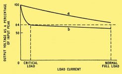
In this application a bleeder would only put more stress on the choke!
LUNDAHL says 5.7 A is the saturation point and the DUNCAN modeler predicts 9 A going through the choke!
Wish LUNDAHL made a BIG one!
I see nothing wrong with being enthusiastic about LUNDAHL products.
LUNDAHL says 5.7 A is the saturation point and the DUNCAN modeler predicts 9 A going through the choke!
Wish LUNDAHL made a BIG one!
I see nothing wrong with being enthusiastic about LUNDAHL products.
So are you saying all of that "extra" voltage is being bled away by those resistors?
And that the SIT 2 is using a much lower voltage power supply?
Yes and Yes.
The SIT-1 is a demonstration of the performance of a single device
surrounded by passive components doing the filtering and current sourcing.
The SIT-2 uses an active current source. As currently shipped, it is a CCS.
Thanks for the confirmation.
I like the passive approach much better than the active one.
So without a choke possibility I will return to being perfectly happy with the amps as they are.
Thanks for your guidance and Happy New Year! Can't wait to find out what you come up with this year!!! Take care,
I like the passive approach much better than the active one.
So without a choke possibility I will return to being perfectly happy with the amps as they are.
Thanks for your guidance and Happy New Year! Can't wait to find out what you come up with this year!!! Take care,
Hello,
All serious publications like the ones in the technical library from Philips company did mention the use of a bleeder in a choke input power supply.if you don't want to use one then just don't. Maybe one day you will hear a strange hissing sound coming from your device. Hope you will have timeenough to switch it off before the safety vent of the power capacitor will start working.
Better be safe than sorry.
Greetings, eduard
still having troubles with Class B Flue , even if I'm feeling sensations of proper A Class one .... so , missing few days of online/reply time
as subject of thread is sayin' - you want choke input PSU , not choke loaded gain stage ....... so it seems Papa misunderstood what you really want
looking at LL2733 datasheet (Lundahl site) , series connection is ditto good for feeding one channel of your SIT
that means one bridge , then LL2733 , then cap bank , all that feeding one SIT-1 channel
you can use one common xformer for both channels , and proper AC Voltage is easiest to determine ( as you did) with Duncan's PSUD
again , fastest info one can get about choke input filtering is to search for NEM AI 50, here and elsewhere on net , you'll find nice graphs of xformer and rectifier loading
lookie : http://www.diyaudio.com/forums/solid-state/161663-nem-ai-50-a.html

edit:
so , as Pa said - you need to shoot for 90Vdc at cap bank , and in your sim set load as 1A4 CCS
as subject of thread is sayin' - you want choke input PSU , not choke loaded gain stage ....... so it seems Papa misunderstood what you really want
looking at LL2733 datasheet (Lundahl site) , series connection is ditto good for feeding one channel of your SIT
that means one bridge , then LL2733 , then cap bank , all that feeding one SIT-1 channel
you can use one common xformer for both channels , and proper AC Voltage is easiest to determine ( as you did) with Duncan's PSUD
again , fastest info one can get about choke input filtering is to search for NEM AI 50, here and elsewhere on net , you'll find nice graphs of xformer and rectifier loading
lookie : http://www.diyaudio.com/forums/solid-state/161663-nem-ai-50-a.html
edit:
so , as Pa said - you need to shoot for 90Vdc at cap bank , and in your sim set load as 1A4 CCS
Last edited:
My friend from Holland gave to me a pair of Lundahl LL2733 made for Thomas Mayer, I have a plan to build choke input filter for my SIT Nemesis amp and I think I still apply zen V3 active supply regulation in this amp😛
Sorry to hear you have the flu (at first I thought you were having chimney problems).
The problem with the LUNDAHL choke is that it is rated for 3.4 A and the DUNCAN AMPS modeler says 9+ amps would be running through the choke. This is assuming I am looking at the thing correctly. (this is now an incorrect statement)
There is only one power transformer (with the secondaries in series) and one bridge rectifier in the amplifier.
I think your calculation is leaving out the current wasted by those resistors and the fact that each SIT1 is a mono amplifier! You must really have the flu!
I went to PSUD2 - (at work) to put in the numbers again to make sure I was not dreaming and have discovered that PSUD does not run properly with UBUNTU/Wine which is what I use at home.
So from what I see here on my Win10 work computer is that the choke will not be overstressed quite as much, but still too much. I now know I cannot use PSUD at home!
The SIT1 seems to drawing FAR more than 1A4!
I did more modeling - this time with two LL2733s in parallel - of course this gives plenty of margin - I now find using 20R as my load - the load I found that gives 90 volts in OEM mode - and I need 175 uF before the choke to get the voltage to 90. 2 x 50 is as large as ANTEK has until you get to tube voltages.
I am showing with the "oem" setup 4.5 amps. 72 volts - 4.2 A power transformer
With the CLC and doubled up chokes - 4.49 amps 100 volts 3 A power transformer
Both output 90 volts with a 20R load.
Does this make any sense?
Thanks for your consideration!
...........
Does this make any sense?
Thanks for your consideration!
nope , it seems you got it all wrong
NB - all those resistors in your SIT-1 amp are there as internal load for SIT part itself
that would be simplest way of making SE amp , load it with pure reactive load (resistors)
so , you really can't mix , explaining and intending - introducing choke input PSU filtering (existing power resistors intact in circuit) vs. introducing choke load (instead of existing power resistors)
and - if they wrote on LL2733 1A7 as steady current figure , you can be sure that it is good for 1A7 of steady current load ........ all peaks and valleys ,you can see in PSUD , taken in account
so , now , at least I'm confused what's real goal here - from now on , my brain demands some sort of sketch .......
LC power supply
Evening all,
I am building a linear power supply for my Q-Watt amp, 200W per channel.
Up to now I was following conventional wisdom (I think):
Then I discovered inductors, potentially used after the rectifier in an inductor input power supply or between the capacitors as a CLC 'pi' filter.
I modelled the latter against the 'bog standard' capacitor configuration above and the results seem too good to be true. I used a 10mH inductor. I know more would be better but I'll never fit in 4x inductors if they are too big. So anyway... results of my quick simulation are attached.
The inductor design has only one 'big' electrolytic cap, and another 1/4 size and yet the ripple is approx. 0.3V.
The dual cap design has 2x 10mF caps and results in 1.4V ripple. Current through the load was approx. 3.2A in both cases; a bit lower in the case of the inductor design as there was an additional 2V dropped due to the lossy inductor.
So... the question to all of you learned folks is... if I can scrounge or make some compact 0.01H inductors, is the CLC architecture a good idea?
Evening all,
I am building a linear power supply for my Q-Watt amp, 200W per channel.
Up to now I was following conventional wisdom (I think):
- Transformer, 2x 432VA
- Bridge Rectifier, 2x 35A
- Capacitor, 2x 10mF
Then I discovered inductors, potentially used after the rectifier in an inductor input power supply or between the capacitors as a CLC 'pi' filter.
I modelled the latter against the 'bog standard' capacitor configuration above and the results seem too good to be true. I used a 10mH inductor. I know more would be better but I'll never fit in 4x inductors if they are too big. So anyway... results of my quick simulation are attached.
The inductor design has only one 'big' electrolytic cap, and another 1/4 size and yet the ripple is approx. 0.3V.
The dual cap design has 2x 10mF caps and results in 1.4V ripple. Current through the load was approx. 3.2A in both cases; a bit lower in the case of the inductor design as there was an additional 2V dropped due to the lossy inductor.
So... the question to all of you learned folks is... if I can scrounge or make some compact 0.01H inductors, is the CLC architecture a good idea?
Attachments

Dear ZM,
I fear my inarticulate electronics jargon is misleading you.
I figured all of those resistors the power flows through on its way to the SIT take their share of the energy resulting in the expected "waste" of energy due to the heroic approach Ing. Pass took with this amplifier.
To make it plain - I am not going to remove or replace any components that comprise the amplifying circuit. Only the power transformer will be swapped and a choke (or two) added - all else will remain the same.
All I know is if you plug the values into PSUD (72 volts 4 A power transformer - I rounded off to 76mF for the reservoir) and adjust the output load until you come up with the output voltage (where I measured, the points marked D and G, I read 40 volts at each, which seems to have been the wrong place to take a reading, I have now used the 90 volts as recommended in your post. The load I use is 20 ohms for the model.
When you do this PSUD says that 4.5 A are passing through that output load.
Is that erroneous? Am I misinterpreting what PSUD is saying?
Thanks for your consideration and hope you are feeling better.
@popchops
yup , good idea
in case that you can manage , you can have better results ( with less space needed) if you put differential choke (two rail windings on same core)
rick , look at this one , as example ;
goal is to have 24Vdc at output , well in range of
NB that , for proper simulation ,generally- you need to input all bloody xformer data (right click on it , edit , then inputting everything what's asked)
Attachments
Last edited:
ZM,
You have me confused.
That looks more like a supply for a J2 or an F5 instead of a SIT1.
What is that choke? The LL2733 is 100 mA and 0.875R.
I always put the transformer data within PSUD which is why I included it in my post.
You have me confused.
That looks more like a supply for a J2 or an F5 instead of a SIT1.
What is that choke? The LL2733 is 100 mA and 0.875R.
I always put the transformer data within PSUD which is why I included it in my post.
didn't I wrote - as example ?
I also said - use CCS as load in your sim
goal is to have 90V across final 1A4 CCS load
I also said - use CCS as load in your sim
goal is to have 90V across final 1A4 CCS load
I guess where I am getting confused is that I do not doubt the SIT (itself) needs 1A4 but I think you are neglecting what those resistors are absorbing.
I have found no difference between a current source load and a resistor as the load in PSUD. You just have to put the resistor values in to find the current value you are looking for. I find it easier to do it this way when I am reverse "engineering".
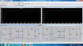
I attached a screenshot of an example - this one is using a single LL2733 and ANTEK has a 500VA 54 X 2 volts - 4.2 A transformer. Not that I want to use a 500 VA transformer but that is where you have to "go" for the voltage. I do not think the choke would survive this duty.
So when I see 4.6 A RMS in the IL1 column what does that mean? I have assumed it is what is passing through the element.
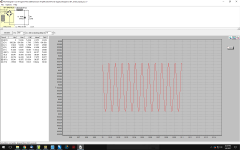
When two chokes are used in parallel the ripple is roughly doubled.
If room could be found for an additional RC filter the ripple goes to 8 mV.
I have found no difference between a current source load and a resistor as the load in PSUD. You just have to put the resistor values in to find the current value you are looking for. I find it easier to do it this way when I am reverse "engineering".
I attached a screenshot of an example - this one is using a single LL2733 and ANTEK has a 500VA 54 X 2 volts - 4.2 A transformer. Not that I want to use a 500 VA transformer but that is where you have to "go" for the voltage. I do not think the choke would survive this duty.
So when I see 4.6 A RMS in the IL1 column what does that mean? I have assumed it is what is passing through the element.
When two chokes are used in parallel the ripple is roughly doubled.
If room could be found for an additional RC filter the ripple goes to 8 mV.
Attachments
Last edited:
- Status
- Not open for further replies.
- Home
- Amplifiers
- Pass Labs
- SIT1 Choke Input Power Supply?