Hello.
I’m Peter for Hungary.
Sorry for my English...
So i have this car amp,missing two fets.
Can anybody help for me?
Service manual or other things.
I’m Peter for Hungary.
Sorry for my English...
So i have this car amp,missing two fets.
Can anybody help for me?
Service manual or other things.
Usually in this architecture IRF640N is used, but in this case, it may not be so.
In all the amplifiers that use this architecture, there are always at least 3 or 4 IRF640N per side (so 6 or 8 pieces in total), never only 2 pieces, so maybe the IRF640N is not enough in this case.
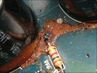
All of that brown fixative must be removed from the board. It's initially light in color. When it turns dark it becomes both conductive and corrosive and can cause the amp to fail or malfunction.
The IRF640N as suggested would be a good starting point to at least get the amp working.
Do you have any experience repairing car amps?
The IRF640N as suggested would be a good starting point to at least get the amp working.
Do you have any experience repairing car amps?
Usually in this architecture IRF640N is used, but in this case, it may not be so.
In all the amplifiers that use this architecture, there are always at least 3 or 4 IRF640N per side (so 6 or 8 pieces in total), never only 2 pieces, so maybe the IRF640N is not enough in this case.
Okay im understand but this is one chanel amp.
Not enough two IRF640N in this case?
All of that brown fixative must be removed from the board. It's initially light in color. When it turns dark it becomes both conductive and corrosive and can cause the amp to fail or malfunction.
The IRF640N as suggested would be a good starting point to at least get the amp working.
Do you have any experience repairing car amps?
What do you mean brown fixative?Please mark with red in my pictures.
Another forums anybody say me the two missing fets is two double side diode?
It is wright?
And yes,i have little experience amp repairing.
In the outher side is four P60NF06 fets and two double diode.
FMG22S and FMG22R.
B0732B76 E121 4045 BBC7 AAC454F32BEF - Kepkuldes - Kepfeltoltes
FMG22S and FMG22R.
B0732B76 E121 4045 BBC7 AAC454F32BEF - Kepkuldes - Kepfeltoltes
It's on various parts from light to dark. It's the brown substance in the attached diagram.
The amp has to have two rectifiers and at least two output transistors. If the two missing were rectifiers, where would the outputs go?
This amp is a smaller version with a slightly modified low-side driver circuit (missing one 5v reg and one optocoupler) of the 1500 diagram I posted. It's more like the amp below.
Attachments
It's on various parts from light to dark. It's the brown substance in the attached diagram.
The amp has to have two rectifiers and at least two output transistors. If the two missing were rectifiers, where would the outputs go?
This amp is a smaller version with a slightly modified low-side driver circuit (missing one 5v reg and one optocoupler) of the 1500 diagram I posted. It's more like the amp below.
You’re right.
Next week pay it for the new fets and tested four P60NF06 its good or bad.
With IRF640N you are certainly going well, there is also the possibility that it is the mosfet that is factory-fitted, but I believe that only one IRF640N is too small.
I say because I see that the power supply is generous, it certainly manages to give you a lot of power, which the single IRF640N hardly succeeds in returning (this could be the reason for the failure).
In my opinion, you could also try IRFB31N20D by lowering the value of the gate resistor to 6,8ohm, or better still IRFB38N20D with 4,7ohm of R gate.
Be careful, this is just my opinion, I haven't tried it myself.
The only advice I can give you is: before carrying out any test, make sure that the entire circuit that drives the mosfets is working and that all the required voltages are present (+/- rail, +/- 12v for OPAMPs, + 5v and +/- 12v for the modulator).
Installing any new mosfet before you have verified all this could lead to instantaneous, disastrous and worse failure than the previous one.
- Home
- General Interest
- Car Audio
- SinusLive sla 500