On the Tung Sol data sheet below for 6BM8 they present an application note for using 6BM8 as a one tube two stage OTL AF amp. Since Svetlana 6BM8 is in current production and I've been trying to decide on a simple one tube OTL amp project, this might be good. However the schematic is short on a few values like the plate choke and supply voltages. Has anyone tried this circuit?
Would anyone might be able to help me determine some suggested starting values for the voltages and choke value, or maybe eliminating the plate choke? I'm a nooby at design but a builder of dozens of tube kits over a 40 year span, trying to get beyond kit building and struggle a little making it interesting.
To drive 300 ohm phones. I did search the forum but couldn't find this application note being tried yet.
https://frank.pocnet.net/sheets/127/6/6BM8.pdf
Sorry, no experience with the circuit you reference but if you will only be driving 300 ohm (or higher) phones one of the Broskie Aikidos might work well for you. My choice would be one of the 9 pin ones for more tube rolling possibilities. 4 tubes instead of 2 in the amp section though.
Steve
All-in-One Aikido Noval with Tube Rectifier
Steve
All-in-One Aikido Noval with Tube Rectifier
How many ohms?
Use the 6BM8 triode as input gain, use the pentode strapped as a triode and use it as a cathode follower. Capacitor couple the headphones to the CF.
Use the 6BM8 triode as input gain, use the pentode strapped as a triode and use it as a cathode follower. Capacitor couple the headphones to the CF.
How many ohms?
Use the 6BM8 triode as input gain, use the pentode strapped as a triode and use it as a cathode follower. Capacitor couple the headphones to the CF.
Thanks, that makes more sense than the circuit shown for headphones.
Sorry, no experience with the circuit you reference but if you will only be driving 300 ohm (or higher) phones one of the Broskie Aikidos might work well for you. My choice would be one of the 9 pin ones for more tube rolling possibilities. 4 tubes instead of 2 in the amp section though.
Steve
All-in-One Aikido Noval with Tube Rectifier
Thanks, I have built this kit but the octal one without the built in rectifier. It works great for headphones. The 6BM8 was just an idea for the next project where I want to depart from kits.
This is the right topology and the electrical properties of the 6BM8 seem to be very suitable for the task. The Aikido and CF are uninteresting. You could try to replace the plate choke with a resistor. Some values need to be determined experimentally. Signal transfer characteristic remains a question.
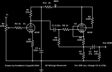
Here's a circuit I threw together. The values might need a bit of tweeking. 6F3P == 6BM8 but NOS Soviet tubes. Much better IMHO.
Thanks I'll try it at some point (its going into my headphone amps file) 🙂
But the Tung Sol application note did depict a plate output. I've done many of these CF with capacitor out circuits and the're fun. But I never tried one from the plate side as an OTL as in the app note.
You're welcome 🙂
Usually the plate output is too hi Z for a load as low as headphones. Thats where other topologies like SRPP and the like come in, right? Also, the datasheet circuit doesn't specify the load... I think there were hi Z headphones back then, no?
Usually the plate output is too hi Z for a load as low as headphones. Thats where other topologies like SRPP and the like come in, right? Also, the datasheet circuit doesn't specify the load... I think there were hi Z headphones back then, no?
Last edited:
kodabmx,
the SRPP is not a single ended topology therefore I dismiss it right off. The common anode topology is in fact a dull topology, which is rather better to avoid as far as possible. We are left with the common cathode amplifier. The intrinsic (output) impedance is a complex impedance that depends on a number of parameters so it can be difficult to predict the outcome in certain bias conditions, right?
the SRPP is not a single ended topology therefore I dismiss it right off. The common anode topology is in fact a dull topology, which is rather better to avoid as far as possible. We are left with the common cathode amplifier. The intrinsic (output) impedance is a complex impedance that depends on a number of parameters so it can be difficult to predict the outcome in certain bias conditions, right?
kodabmx,
for the sake of forceful signal transmission.
Thats what impedance matching is about. Since the output impedance at the anode is likely to be in the 1,000s of ohms while the cathode output impedance is more likely in the 100s of ohms (haven't done the math, but thats a good enough estimate for our purposes here) and the headphones are likely to be in the 32 - 600 ohm range, cathode follower is the better choice (not sure if its optimal).
kodabmx,
the SRPP is not a single ended topology therefore I dismiss it right off. The common anode topology is in fact a dull topology, which is rather better to avoid as far as possible. We are left with the common cathode amplifier. The intrinsic (output) impedance is a complex impedance that depends on a number of parameters so it can be difficult to predict the outcome in certain bias conditions, right?
pretty sure you have missed the point. The OP has asked about an OTL implimentation ie no output transformer. Regardless of how complex the impedance calculation might be, in reality the orders of magnitude tell you that cathode follower or perhaps SRPP or Mu follower are your choices.
On the Tung Sol data sheet below for 6BM8 they present an application note for using 6BM8 as a one tube two stage OTL AF amp....
https://frank.pocnet.net/sheets/127/6/6BM8.pdf
You can work-out appropriate operating point by stealing from the datasheet (the other, complete, datasheets).
That's not even a good plan. The output impedance is HIGH. Distortion is not controlled. The choke has to be 40mA with more inductance than the load at the lowest frequency of interest, which may be shockingly high. And in raw materials, a choke is "same cost" as a transformer (which gives better impedance fit); except a one-winding choke may be a standard part and out selection of two-winding transformers is limited.
Still, a 5k-7k:16 transformer, which can be found, makes a far better audio amplifier for headphones.
Without transformer: the pentode can only idle near 40mA. So the peak output in 32r is less than 1.3V, and the maximum power around 25 milliWatts. Audible, but not worth the effort. It gets better at 300 Ohms, plenty loud, but not as clean as we'd like.
I suspect this one is aimed at Servos, little motors, which were a big thing in the 1950s, and do not need a lot of linearity or damping. (Yes, it does say "audio", but there was a lot of overlap audio/servo.)
- Home
- Amplifiers
- Tubes / Valves
- Single tube per channel 6BM8 OTL for headphone amp