Hi. I've been going back and forth between dual and single sided supplies, but I'm not satisfied with any of my current solution. I've mostly worked with chip amps and op-amps with output stages (also mostly headphone amplifiers). What I have found is that running it off a single supply is quite satisfying, the amp seems stable and there aren't many unsuspected surprises. I'm not quite fond of the output capacitor though. It's big, and they will often require output relays, comparator, timing circuit and all that. The amplifier is also susceptible to power supply noise as the non-inverting input is biased to 1/2 supply with a voltage divider (I assume I can put some voltage reference IC there, haven't tried that).
It's all great and dandy when using a center tapped mains transformer, but when dealing with headphone amplifiers it's quite satisfying to use a wall wart, but dual sided wall warts are not common 🙁 I've previously made some amps using a virtual ground, but I don't find this satisfying either. I constantly read negative things about virtual ground solution, that they add distortion etc. I personally find that my simple voltage divider and buffer capacitor to drift off center (as they will if the current draw is unequal). I know there are virtual ground chips, but they have limited current capabilities. Maybe it's possible to add some output transistors to these virtual ground chips, but I'm not sure how good that solution is. What I'm asking is if there is a satisfying way of making a low powered amplifier using a wall wart as a psu while keeping the psu noise to a minimum (without using a regulator)?
Thank you for any replies 🙂
an active supply splitter can be a solution where you don't need efficiency
"3-channel" is subtely different and adds unneeded noise, possible distortion, crosstalk
"3-channel" is subtely different and adds unneeded noise, possible distortion, crosstalk
What I'm asking is if there is a satisfying way of making a low powered amplifier using a wall wart as a psu while keeping the psu noise to a minimum (without using a regulator)?
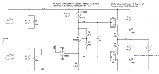
For the sensitive singleton input I usually use current source on the positive side, just to isolate the amplifying transistor from the power supply.
jcx: I see your circuit and I've been thinking of making something like that. I would need a class AB output stage of U1 though as I can't find a op-amp that can handle enough current. I'm bound to believe that this will lead to distortion though 🙁
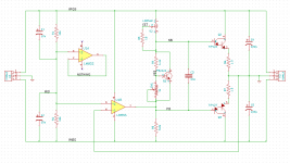
I just tried making a TPA6120 amplifier using a virtual ground. Here's my schematic (as it is currently soldered on the board):
http://i40.tinypic.com/2m0gpe.png
C2, C3, C1, C6: 470nF
C4, C5: 220uF
R7, R8: 100kOhm
R3, R5: 10kOhm
R6, R9: 10Ohm
The amp is stable, no sign of oscillation. When I first connected it to power, the virtual ground was at 1/2 supply, then suddenly it drifted to about +10V -2V. Next day, the virtual ground was again stable at +-6V. I then soldered on the input jack and volume pot and bang, +10V -2V :S For the virtual ground to drift like that there HAS to be a current flowing from ground to +V, but looking at the schematic, this is impossible. Unless the TPA6120 will allow considerable current to flow through it's non-inverting input, I have no idea of how this is happening. This sort of pisses me off as I can never find a solution to it 🙁
Last edited:
For the sensitive singleton input I usually use current source on the positive side, just to isolate the amplifying transistor from the power supply.
I didn't quite understand that. What's a sensitive singleton input?
Use a chipamp. It will give low impedance and should have plenty of current capability to balance out the imbalance between +ve and -ve current draw................ I would need a class AB output stage of U1 though as I can't find a op-amp that can handle enough current......................
Remember to include HF and MF decoupling at both the opamp power pins and the chipamp power pins.
Last edited:
I didn't quite understand that. What's a sensitive singleton input?
I mean one transistor as input amplifier, is sensitive to power supply noise. Always use a pair, one as a current source, just to separate the other one from PSU ripple.
Use a chipamp. It will give low impedance and should have plenty of current capability to balance out the imbalance between +ve and -ve current draw.
Remember to include HF and MF decoupling at both the opamp power pins and the chipamp power pins.
Which unity gain stable chip amp would that be Andrew 😉
The part to use is BUF634 but they are not cheap.
Have a look at this project, originally designed for line level circuits but will cope with a headphone amp.
richie00boy: I will try and build that circuit, it's still about as simple creating the virtual ground with a power amp and definitely more simple than having an output capacitor, comparator and output relay's 🙂 I'm a little curious about it's output current capabilities though, but I guess the only thing really limiting the current are the 10Ohm resistors (assuming that the Hfe is high enough)?
Yes that's right, 10 ohms. The transistors were selected because of decent gain. The next level up from that would be to apply that output stage to an op-amp and put a feedback round it all.
What is wrong with using an AC wall transformer and then building a full wave voltage doubler and grounding at the center. You can then regulate the resulting + & - rails and have a stable ground reference.
9 VAC transformers are used all of the time for old answering machines. That would give you + 12 and - 12 before regulation.
9 VAC transformers are used all of the time for old answering machines. That would give you + 12 and - 12 before regulation.
I must be wrong. I seem to recall a few schematics showing a chipamp for this duty.Which unity gain stable chip amp would that be Andrew 😉
Any chipamp capable to work in a single supply mode is a rail splitter directly.
Just remove the output cap and there you have it - dont you?
For ex. TDA2030 in single supply, check data sheet...
Just remove the output cap and there you have it - dont you?
For ex. TDA2030 in single supply, check data sheet...
Last edited:
Well that's a creative way of thinking about it. I guess there is the potential for noise pickup from the "unused" input being amplified by the gain, but actually it's probably not a big concern.
Hi Plecto,
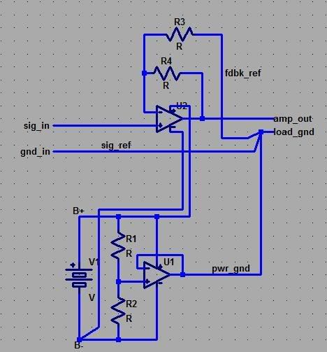
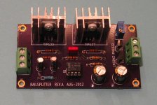
I built a virtual ground generator / "rail splitter" last year. Mine used TIP122 / TIP127 complementary Darlingtons in the output stage, and is designed to deliver ± 1 amp load current to or from the virtual ground. Schematics and LTSPICE simulation are attached; you'll see that I used the LM833 opamp, whose GBW product is 10 MHz.
I ordered several boards and many sets of parts, so, as it happens, I've got an extra unit, fully assembled and tested, which I'd be glad to give you for free. PM me with your (North America only, sorry) mailing address and I'll send you the board. Then you can try it out to see how well you like it in real life, with your music and your other equipment.
MarkJ
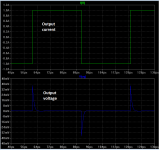
Attachments
jcx: I see your circuit and I've been thinking of making something like that. I would need a class AB output stage of U1 though as I can't find a op-amp that can handle enough current. I'm bound to believe that this will lead to distortion though 🙁
I just tried making a TPA6120 amplifier using a virtual ground. Here's my schematic (as it is currently soldered on the board):
http://i40.tinypic.com/2m0gpe.png
C2, C3, C1, C6: 470nF
C4, C5: 220uF
R7, R8: 100kOhm
R3, R5: 10kOhm
R6, R9: 10Ohm
The amp is stable, no sign of oscillation. When I first connected it to power, the virtual ground was at 1/2 supply, then suddenly it drifted to about +10V -2V. Next day, the virtual ground was again stable at +-6V. I then soldered on the input jack and volume pot and bang, +10V -2V :S For the virtual ground to drift like that there HAS to be a current flowing from ground to +V, but looking at the schematic, this is impossible. Unless the TPA6120 will allow considerable current to flow through it's non-inverting input, I have no idea of how this is happening. This sort of pisses me off as I can never find a solution to it 🙁
You don't say what R1 and R4 (the virtual ground voltage divider) are. What are they? Have you tried something lower?
All opamps have current flowing from/to the inputs, this is "input bias current". Unfortunately, the data sheet for the TPA6120 does not specify what this is. You can and must assume that there is some (essentially DC) current flowing from both inputs, and this will affect your virtual ground. The easiest fix is to lower R1 & R4 so that the current flowing through them is >> bias current.
A half wave voltage doubler off a 9V AC wall wart will do for most headphone things.
If you want to get fancy, the TLE2426CD gets the job done (Note that graph concerning required value of output decoupling cap for stability however), I use them extensively in preamps down at the few nV/sqrt (hz) level, and they do fine.
However, a better answer is probably to use a unity gain opamp between the mid rail reference and the headphone connector ring.
This ensures that this node is held at the reference voltage while ensuring that only tiny current flows in the reference connection, as all the load current flows rail to rail rather then rail to reference.
Note that when generating a mid rail reference a fairly butch cap across one of the resistors is a good idea to reduce the thermal noise inherent in the resistor (Particularly if going for a high value resistor pair for current consumption reasons).
It is not a difficult problem to solve, but then I tend to consider that a headphone amp is not something to get too excited about, each to their own.
Regards, Dan.
- Status
- Not open for further replies.
- Home
- Amplifiers
- Power Supplies
- Single supply vs. dual supply and noise, I can't find a proper solution