Dunno re 1875... Rod Elliot has a decent circuit for the 1875.
Although the Data sheet one is pretty well as good as it gets.
Why reinvent the wheel?
Beyond that, Elliot stated that the 1875 makes a decent . . But not great amp.
Have done and used the 1875, for some time now.
He is absolutely right in his assesment /prediction..
Although the Data sheet one is pretty well as good as it gets.
Why reinvent the wheel?
Beyond that, Elliot stated that the 1875 makes a decent . . But not great amp.
Have done and used the 1875, for some time now.
He is absolutely right in his assesment /prediction..

Thanks all. I believe Rod Elliot design is based on dual rails design not a single supply design. I don't think we are trying to reinvent the wheel since it's continuing development from data sheet and existing info on various forums/ sites. Why? Certainly, it's just "hobbies" to have fun tweak to test. Don't we all enjoy that 🙂.
My previous project was an inverted dual-rails LM3886 and I ran into stability issues but have resolved thanks to many forum members (esp. Tom from Neurochrome). I have problems with the feedback network and fried the Zobel resistors several time. Looking back, I also have high absolute value feedback resistor (220k/7.5k), but it's stable now so I left as it is. For this project, I'd like to pay more attention to stability.
My previous project was an inverted dual-rails LM3886 and I ran into stability issues but have resolved thanks to many forum members (esp. Tom from Neurochrome). I have problems with the feedback network and fried the Zobel resistors several time. Looking back, I also have high absolute value feedback resistor (220k/7.5k), but it's stable now so I left as it is. For this project, I'd like to pay more attention to stability.
Layout and in particular how you configure the grounds is all important.I'd like to pay more attention to stability.
I always look at the problem of grounding from a DC perspective. Add imaginary track and wire resistance, crazy values like 1 ohm and then ask yourself if the amplifier is delivering say 1 amp load current will that current in any way modify what you would expect.
This might look strange but it shows the problems.
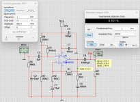
Here is the chip amp working perfectly with LT's zero ohm wires. Output set to 10 volts pk/pk

Now we go silly... but this is what folk do when laying out boards and so on. Look at all the 1 ohm resistors added now. There are zillions of possibilities for errors and I've made one basic but correct assumption and that is for minimum distortion and best possible performance the input and feedback return must be one and the same point. They have to be. So lets call that our reference pint to which all others are referenced.
We now have a big problem here because although our chip is nicely decoupled it still sees a high impedance relative to the reference point and this pin of the chip is seeing large voltage changes in response to load current. In practice it all just goes bang as the chip oscillates.

If we take the high current supply for chips negative terminal and return it to the reference point things get a whole lot better but notice the weird 'shift' in output level. This is AC coupled so how can that be? It looks like second harmonic distortion is making the output asymmetrical.

The above has just 100uF across the chip but look at all the 1 ohms added together before the supply even reaches that pin. We have a massive 7 ohms... and yet it basically works OK now.
Lets smooth that supply across the chip. Now we are almost there:

Finally we can return the load to the power supply. The 1 ohms are all wiring resistances. Now we have our -/+10 v pk/pk signal back and the ground point (our reference we measure to and from) remains at the input. The wiring resistance and its problems have 'disappeared'.

Here is the chip amp working perfectly with LT's zero ohm wires. Output set to 10 volts pk/pk
Now we go silly... but this is what folk do when laying out boards and so on. Look at all the 1 ohm resistors added now. There are zillions of possibilities for errors and I've made one basic but correct assumption and that is for minimum distortion and best possible performance the input and feedback return must be one and the same point. They have to be. So lets call that our reference pint to which all others are referenced.
We now have a big problem here because although our chip is nicely decoupled it still sees a high impedance relative to the reference point and this pin of the chip is seeing large voltage changes in response to load current. In practice it all just goes bang as the chip oscillates.
If we take the high current supply for chips negative terminal and return it to the reference point things get a whole lot better but notice the weird 'shift' in output level. This is AC coupled so how can that be? It looks like second harmonic distortion is making the output asymmetrical.
The above has just 100uF across the chip but look at all the 1 ohms added together before the supply even reaches that pin. We have a massive 7 ohms... and yet it basically works OK now.
Lets smooth that supply across the chip. Now we are almost there:
Finally we can return the load to the power supply. The 1 ohms are all wiring resistances. Now we have our -/+10 v pk/pk signal back and the ground point (our reference we measure to and from) remains at the input. The wiring resistance and its problems have 'disappeared'.
Attachments
I'm not a big fan of predicting oscillations with simulation. Any simulation is missing parts and has parts that are not there.
- Home
- Amplifiers
- Chip Amps
- Single supply LM1875 design