So, I'm looking to build a solid-state attenuator based on the DS1882. Analog design is not my strong suit, so I'm hoping someone can help me out here.
The DS1882 wants to drive a high input impedance, and the amp I'll be using only has 20kΩ. So, it suggests in the datasheet using buffers (op amp voltage followers) between the output of the DS1882 and the input of the amp. (Check out the data sheet.)
Only thing is, I wasn't planning to have negative voltage in the unit.
So, what would y'all do?
Does configuring an op amp with a single supply provide acceptable behavior in audio applications?
Should I just go ahead and plan to use a ±12V supply?
Are there other types of buffers to explore?
can the output of the ds1882 drive the 20k||parasitic capacitances in the connection?
I suspect that 20k is already a high enough load impedance, it's the parasitic capacitances that may be a bigger problem.
Short, or very short, or ultra short trace/cable will have less capacitance
I suspect that 20k is already a high enough load impedance, it's the parasitic capacitances that may be a bigger problem.
Short, or very short, or ultra short trace/cable will have less capacitance
The DS1882 wants to drive a high input impedance, and the amp I'll be using only has 20kΩ.
Does configuring an op amp with a single supply provide acceptable behavior in audio applications?
Should I just go ahead and plan to use a ±12V supply?
The pot value is 45k, so you do need a high input impedance amplifier, or a buffer before it. You can use a single supply op amp,
and many do, at the cost of half the output voltage swing, and the necessary coupling caps at the buffer input and output.
I'd go with the dual supply if you want the best performance.
I'll guess a voltage follower made of almost any opamp will do the job. TL071 and up in performance.
OPA134, NE5532/34, and lot's of other types. OPA627, AD8610, LT1115, LT1028, AD797, LME49990 etc. expensive and good.
OPA134, NE5532/34, and lot's of other types. OPA627, AD8610, LT1115, LT1028, AD797, LME49990 etc. expensive and good.
Are there other types of buffers to explore?
A buffer by definition has 100% feedback. The result is unity gain, very high input impedance, very low output impedance, and distortion in the 3-decimal or better range (i.e. pretty much none).
There's always another way to do something, but a buffer = a buffer.
.
.
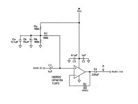
Most commonly used audio op amps can run on a single voltage. The trick--to call it that--is to bias the non-inverting input to 1/2 supply voltage. This puts the op amp itself (and the entire audio circuit) at 1/2 supply voltage, so it actually is running on a dual voltage. The power supply becomes the positive side, ground becomes the negative side.
Here Ra and Rb are a voltage divider that provides the 1/2 supply voltage bias. Ca and Cb form a necessary decoupling/bypass network.
Although it's not obvious, R1 and C1 are the usual high pass filter, their values are calculated in the usual way. Here C1 is shown as larger than you might expect because this gives a theoretical noise advantage, but it could just as well be, say, an 0.47 film capacitor.
R2 is a just-in-case resistor that can help prevent oscillation under some conditions.
C2 and C3 are the decoupling/bypass capacitors usually called for in data sheets.
C4 is a necessary DC blocking capacitor. Together C1 and C4 isolate the biased audio circuit from preceding and following stages that are not biased.
NOTE that C4 needs a discharge path to ground, or it will slowly charge to bias voltage and the whole thing will mysteriously stop working. If there's no following resistance to ground then provide one, maybe 50k at point A.
Note also that if you're positive the following amp is AC coupled, then C4 is not needed, nor is its discharge resistor. The high pass filter on the amp's input takes their place. But be sure.
Op amp suggestions are provided, but as peranders points out there are many that can serve your purpose.
.
Attachments
Last edited:
Wow, guys. Thanks for the help. Thanks in particular to bentsnake for the straightforward explanation.
I going to go ahead and use a single-supply approach (now that I feel comfortable in my understanding), so I don't have to change anything external to the attenuator circuit.
I going to go ahead and use a single-supply approach (now that I feel comfortable in my understanding), so I don't have to change anything external to the attenuator circuit.
Glad to help out a bit. I probably should have stated more clearly that R1 sets the input impedance (here 100k), the output impedance is single-digit at the op amp's output pin.
Any particular reason I couldn't/shouldn't increase R1 and decrease C1 proportionately? How far can/should I go?
Does the ds1882 expect the ground for its logic circuits to be the same as its signal ground?
If so, will it still work to use a single supply with a ground created from a voltage divider? The V- pin is supposed to be at least 4V below ground. I think it would be easier to just use +/- 5V with an op amp known to be happy on such a supply.
If so, will it still work to use a single supply with a ground created from a voltage divider? The V- pin is supposed to be at least 4V below ground. I think it would be easier to just use +/- 5V with an op amp known to be happy on such a supply.
Yeah, I was actually about to ask that to.
I have +12 Vdc in the enclosure, but I concluded from my last reading of the data sheet that I need ±5 Vdc for the DS1882. That's fine, since there is no shortage of dual output dc-dc converters to do that. So, that means I have either +12 or ±5 Vdc to power whatever buffer I use.
What are some audio op amps that deliver good performance with ±5 V supply?
Any particular reason I couldn't/shouldn't increase R1 and decrease C1 proportionately? How far can/should I go?
If you need a higher input impedance, sure, fire away. The circuit shown should be good for up to around 1meg in, but getting much above 100k runs into noise (Johnson noise, meaning the unavoidable noise resistors make when current flows through them.) Here's a calculator. Guitar Pedals: R-C Filter Calculator
You two are going to work out the DAC thing, right? I know nothing about digital.
.
It's not a DAC, it's a digital trim pot. 🙂
His question was "...will it still work to use a single supply with a ground created from a voltage divider?"
I should think so, because the only place where "ground" is anything other than system ground is within the op amp feedback network, which is ac coupled on both ends. The DS1882 ground is actual ground, although that is also where the op amp Vs- is connected to.
But then again, I'm a digital guy so I'm probably wrong. 🙂
However, either way he's right that my circuit will have ±5 Vdc, so I can run my op amp buffers in normal dual(?) supply mode, at the expense of ±1 Vdc on my supply rails. Whether this will make a difference in THD+N depends on the op amp, I suppose.
Right now I'm looking at the OPA1662's datasheet, which is giving me the impression it will do well with ±5V and the attenuated input signal which will be (as a practical matter) generally coming out of the DS1882.
Last edited:
His question was "...will it still work to use a single supply with a ground created from a voltage divider?"
I should think so, because the only place where "ground" is anything other than system ground is within the op amp feedback network, which is ac coupled on both ends. The DS1882 ground is actual ground, although that is also where the op amp Vs- is connected to.
But then again, I'm a digital guy so I'm probably wrong.
Actually, as it turns our you're right, at least in audio terms. You could cascade a series of single-supply amps running at different supply voltages--and therefore different 1/2 supply voltages--and it wouldn't matter at all to the AC audio signal. In fact, musicians do this all the time with a succession of battery powered "stomp boxes." (you stomp on the box to hit a foot switch)
However, enter the real-world fact of capacitor leakage, which is unavoidable. We're talking in the microamp range, but how/if this might affect your digital carryings on I don't know.
<< Whether this will make a difference in THD+N... >>
In this age of little black chips distortion is worried about far too much. You can't hear 3-decimal distortion, in fact it takes a pretty good scope to even see it. The 0.00006% distortion claimed for the OPA1662 is semi-fictional because there are no instruments that can measure that low, TI just claims it on grounds of "nobody can prove we're wrong." Except among those who say they can hear a difference between gold and silver speaker wires (no, I'm not kidding), distortion in op amps has been a non-issue since the NE5532 came out, what, some 40 years ago.
To belabor that point just a bit, look at the frequency response graph for any given audio chip, which is flat from here to there. Now look at the graph for any given speaker or headphone, which is not so very flat at all. Any distortion you hear today is not from the amplifier.
<< my circuit will have ±5 Vdc, so I can run my op amp buffers in normal dual(?) supply mode >>
"Single supply" is a misnomer. Emphasizing that I'm not selling anything, the circuit in post #6 is running in normal/dual supply mode.
The voltage divider (Ra and Rb) creates what's called a "virtual ground" at 1/2 supply voltage. Assuming a 12 volt supply, the electrical effect is that the op amp's + power pin sees +6 volts, the op amp's - power pin sees -6 volts, and the 50% in between voltage appears to the op amp (and the rest of the circuit) as zero-volt ground. Dual supply all sameO.
However, running a dual supply (as opposed to a virtual ground dual supply) has the advantage of fewer parts and therefore less complexity, which is always good. But now you're getting into SMDs (surface mount devices), which are small, really small. I guess it depends on whether you can, or want to, deal with these.
.
I have +12 Vdc in the enclosure, but I concluded from my last reading of the data sheet that I need ±5 Vdc for the DS1882. That's fine, since there is no shortage of dual output dc-dc converters to do that. So, that means I have either +12 or ±5 Vdc to power whatever buffer I use.
Um? +/-5VDC will run the NE5532 and some other audio op amps that are not SMD.
.
Um? +/-5VDC will run the NE5532 and some other audio op amps that are not SMD.
.
OK. I don't know squat about op amps when it comes to audio performance. All I know is what whichever datasheets I look at tell me. 🙂
I do get that "single supply" is really a misnomer. Potentials are inherently relative, after all. But 10V is still less than 12V.
Another question: for a "non-single supply" op amp buffer (i.e. when Vs- is negative rather than ground), is there any supporting circuitry I should use? I've seen a couple examples for unity gain configurations which have basically nothing other than the op amp itself.
Last edited:
.
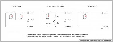
I think maybe a big part of the problem is that people (sometimes including me) use terms so loosely as to make them near-meaningless. Please take the pop quiz, and look at the posted illustration. Especially look at the indicated voltages.
Pop quiz:
We in agreement so far? At all?
Item of information: None of the op amps mentioned in this thread will run on a single voltage. That is, with a positive voltage on the positive supply pin, and ground on the negative supply pin. The op amp will not run, it will just sit there, possibly smoking.
While looking at the illustration below realize than any power supply can be thought of as a battery pack that never runs down. Given the right voltage, any power supply should just plug into any circuit.
.
I think maybe a big part of the problem is that people (sometimes including me) use terms so loosely as to make them near-meaningless. Please take the pop quiz, and look at the posted illustration. Especially look at the indicated voltages.
Pop quiz:
Q1: What's the one certainty about ground?
A1: It's where the black test lead goes. Positive or negative doesn't enter in, ground is just where the black test lead goes.
Q2: How do we know ground when we see it?
A3: Because it's labeled that way on the schematic, and for no other reason. The circuit designer defines a point to call ground, and s/his decision is not arguable.
Q3: Why is ground zero volts?
A3: Because we say so. It's just a matter of agreement.
The above applies to every circuit, everywhere. Dual, single, whatever doesn't enter in, the above always applies.A1: It's where the black test lead goes. Positive or negative doesn't enter in, ground is just where the black test lead goes.
Q2: How do we know ground when we see it?
A3: Because it's labeled that way on the schematic, and for no other reason. The circuit designer defines a point to call ground, and s/his decision is not arguable.
Q3: Why is ground zero volts?
A3: Because we say so. It's just a matter of agreement.
We in agreement so far? At all?
Item of information: None of the op amps mentioned in this thread will run on a single voltage. That is, with a positive voltage on the positive supply pin, and ground on the negative supply pin. The op amp will not run, it will just sit there, possibly smoking.
While looking at the illustration below realize than any power supply can be thought of as a battery pack that never runs down. Given the right voltage, any power supply should just plug into any circuit.
.
Attachments
10V is still less than 12V
That would seem to be correct. But it doesn't obviously relate to the fact that +/-5VDC will run the NE5532, and some other audio op amps that are not SMD.
.
That would seem to be correct. But it doesn't obviously relate to the fact that +/-5VDC will run the NE5532, and some other audio op amps that are not SMD.
.
Right, but that's precisely what I was asking.
Also, whether external circuitry is needed for an op amp buffer which is running from ±5V.
.
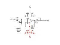
The first illustration below is from post #6. It's there just for comparison.
The second illustration is the same circuit altered to run on a dual supply (such as +/-5VDC). The parts that are different are called out in red. The notes from post #6 apply. Note that C2, C3, C5, and C6 are to be located close to the op amp power pins.
The whole point of these little black chips is simplicity. The complicated engineering is all on the inside, we just have to hook up a few resistors and capacitors. So no there are no additional components, in fact a lot of people would leave out R2.
.
Attachments

- Status
- Not open for further replies.
- Home
- Source & Line
- Analog Line Level
- Single-supply buffer help