here are a two links that will help you,
Parallel Plate Capacitor Capacitance Calculator
Electronics 2000 | Reactance Calculator
Once you determine your capacitance then you must add that to the transformers capacitance and use that value to find the capacitance reactance (at 20khz) and divide that by the turns ratio squared and then you will have the impedance presented to the amplifier.
jer 🙂
Hi Gerald,
Thanks - but how do I know how loud it'll play with a given voltage? I'm currently designing the headphone amplifier and it would be feasible to know if I can expect to output 1 mA or 50 mA to reach a moderately high SPL ... I actually don't know ...
BTW, there won't be a transformer on the output of the headphone amplifier. It's a single-ended transistor circuit where one of the stators are grounded.
A smile for you as well 🙂
Jesper
Here is another great calculator that can help you,
Electrostatic Loudspeaker (ESL) Simulator
50V!?
Have you tried driving your panel with that?
I am thinking that you will need at least 4 times that to get a decent output.
I used a 500v bias an my micro driver and it had about .032" D/S.
jer🙂
Electrostatic Loudspeaker (ESL) Simulator
50V!?
Have you tried driving your panel with that?
I am thinking that you will need at least 4 times that to get a decent output.
I used a 500v bias an my micro driver and it had about .032" D/S.
jer🙂
Last edited:

Hi again,
Still in the process of doing the headphones as a question came up which I hope one of you may just know about:
Suppose I design the electrostatic headphone to have spacers of 0.6 mm between the membrane and the stators and a membrane area of about 50 cm2 do you know what the current requirements for the headphone amp will be (I don't play loud and aim at a 50 Vpp maximum output level)?
Regards from autumn Denmark,
Jesper
Hi Gentlevoice,
There is no way that 50Vpp is going to be enough. With a +/-300Vpp on my amp, my headphones with 0.6 mm spacers are just barely loud enough.
How high bias voltage are you aiming at? I use 580V like Stax.
Wachara C.
Hey Gerald,
Thanks again - looks very ingenious what you are making ;-) Is it a credit card you use for the membrane frame ....?
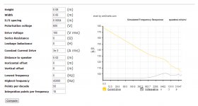
I've made some calculations using the simulator you posted a link to and the max SPL with 0.4 mm spacers and 100V RMS is about 92 dBs with some rise in the higher frequencies. I don't listen to music at very high levels so I would say that this is sufficient.
Also, given that I don't listen at high SPLs I reckon it's not necessary to have a thicker spacer than 0.4 mm (?) - that would also help on max SPLs with a somewhat lower output voltage. Maybe the spacer can even be thinner ...?
FYI I've attached the simulation values I've entered. Interestingly, the closer my ear is to the stator, the more linear the headphone seems to become....
Can I ask you what your simulation figures are?
Greetings from Denmark,
Jesper
Thanks again - looks very ingenious what you are making ;-) Is it a credit card you use for the membrane frame ....?
I've made some calculations using the simulator you posted a link to and the max SPL with 0.4 mm spacers and 100V RMS is about 92 dBs with some rise in the higher frequencies. I don't listen to music at very high levels so I would say that this is sufficient.
Also, given that I don't listen at high SPLs I reckon it's not necessary to have a thicker spacer than 0.4 mm (?) - that would also help on max SPLs with a somewhat lower output voltage. Maybe the spacer can even be thinner ...?
FYI I've attached the simulation values I've entered. Interestingly, the closer my ear is to the stator, the more linear the headphone seems to become....
Can I ask you what your simulation figures are?
Greetings from Denmark,
Jesper
Attachments
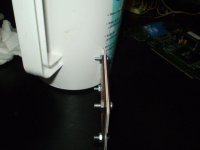
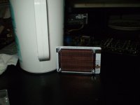
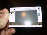
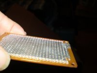
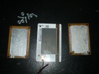
Yes I used some Gift Card credit cards for the frame.
The diaphragm size is 59mm X 44mm and the D/S is .0325"
The diaphragm material is some .1 mil mylar that I got from Chemplex Cat.No: 100 .
I also have some .06mil stuff from them as well but i haven't tried it yet, Chemplex Cat.No: 090 .
For the coating I used Licron this was before I had gotten the Crystal formula which is more clear and much much thinner than the regular Licron.
I ran about a 500v bias on it from a tube amp chassis that I had laying around and I used the transformer in it to drive it as well.
I don't know off hand what the turns ratio was but it was a OPT for a pair of EL34's.
I didn't mess with it for very long and I only made the one.
I ended up taking it apart for the pictures But I still have it and it can be reassembled at anytime.
The sound was very good and clean and it got to a nice comfortable volume.
I didn't have a SPL meter at the time.
I was amazed that when there was bass there was bass and was not boomy at all.
At first I thought that it lacked some high end but it was the Youtube video I was listening to that was poor in quality.
I had found other material that was much better and I had not noticed this before until I was listening to this driver.
Getting back into this hobby after 7 years it was the first driver I had running and then I finally got my little ESL panels going about a month later.
Yes when you are right on the diaphragm it will have a flat response.
As you back away from it you will get a rising response at about 6db per octave.
This true for any dipole driver.
Hi both 🙂
@Wachara: Good to hear from you again, Wachara. Hmmm... 300 Vpp is much higher than I hoped to use - but when entering the difference between 0.6 mm D/S spacing and 0.4 mm spacing in the quadesl simulator it's actually more or less the same as doubling the voltage in terms of the SPL output. So I think I'll try with ~100Vpp and then reducing the D/S distance. If it doesn't play very loud I know what could be the issue .... I also use a 0.9 um membrane so probably that also helps in terms of increasing SPL?
@Gerald: Thanks for elaborating ;-) I don't know what the materials you used are composed of (you might look at my signature ;-)) but in Wachara's thread on ESL headphone design he - or one of the other posters - mentions using normal wood glue (if I remember correctly) for membrane covering. However, I still need to try this out because it seems that the membrane I use already builds up static electricity on its own so maybe it's not needed to cover it .... will have to experiment with that. Back to building ...
Thanks again both of you for replying,
Jesper
The diaphragm thickness has no bearing on how loud they will play as this is strictly a function of the operating voltages and the D/S.
Every time you double the D/S you have to increase you voltages by 4 in order to have the same SPL.
The other trade off is How much excursion room you need for the bass frequency's as for every octave lower the excursion increases 4 times for the same SPL.
I have not tried the PVA glue trick yet But I hear it works well and I will be using it on my next build to see how well it works.
I did do some simple test with it a while back but never used it on a Diaphragm as of yet.
Here are some links to that discussion,
http://www.diyaudio.com/forums/planars-exotics/109789-esl-diaphragm-coating-7.html#post2078272
http://www.diyaudio.com/forums/planars-exotics/109789-esl-diaphragm-coating-7.html#post2081597
http://www.diyaudio.com/forums/planars-exotics/109789-esl-diaphragm-coating-6.html#post2053289
The materials I used are just plastics, PCB material,aluminium duct tape, clear acrylic enamel as a stater insulation and Licron from Techspray as the diaphragm coating.
Also, I used double sided transparent tape to mount the Diaphragm to the frame.
jer 🙂
Last edited:
Just for you know, I stop using PVA glue as the coating material. The glue is very humidity sensitive. It can attract too much moisture from the air and cause all kinds of problem.
Wachara C.
Wachara C.
Hi both,
- again thank you for your replies. I'll be getting back to the membrane coating shortly, however, right now have a slight challenge finding - hopefully good-sounding - low signal transistors that can be used for a higher-than-expected-voltage electrostatic headphone amplifier. Can I ask you if you both use tube amplifiers?
@Wachara: Can I ask you what you use for membrane coating now?
@Gerald: I've taken a look at the Licron MSDS sheet and it is classified as a safety class 4-1 product here in Denmark. Which is a quite safety requiring material (when disposed of it should e.g. also be marked as containing potentially carcinogenic substances). So, if possible, I'd like to find a less "active" material to cover my membranes, although I might get back to it if I can't find such a material. But thanks for suggesting ;-)
Greetings,
Jesper
At the moment I use transformers for my ESL's.
I will be exploring some some direct drive methods in the future.
I have built a FET type amp for around 200v using stacked up IRF510's and single FET's such as the IRF740 and IRF840's.
It worked but I did not test it on an ESL yet as this was two years before I had gotten one back running again.
So I don't have a complete design but I did post a schematic of what I was working with in another thread.
These might help to give you some idea's,
http://www.diyaudio.com/forums/head...discrete-class-headphone-amp.html#post2596223
http://www.diyaudio.com/forums/planars-exotics/221050-looking-hv-fets-direct-drive.html#post3192308
jer 🙂
I now use this:


The gel is much better than the spray.
It has been working very well for my headphones.
About the amp, I use tube amp.
Wachara C.
The gel is much better than the spray.
It has been working very well for my headphones.
About the amp, I use tube amp.
Wachara C.
🙂😛😀🙄
Wachara your images made me smile 🙂 I guess DIY audio allows for much creativity in finding solutions to things 😉 ... And if I remember correctly you live in Thailand where humidities can be quite high so if this works in Thailand I guess it may also work in most other places ... (I hope)
However, when looking at the images I cannot see which company makes this? Might I ask you to just briefly post about who makes it?
@geraldfryjr: Hey Gerald. Thanks again for posting and linking. However, for now I'm not too keen on using either ICs or FETs in the signalpath and unless I missed something in the threads you link to they use either one or a mix of both (right?).
What just spurs my interest, though, is that the electronics design looks like the one I saw when I looked into plasma headphones. Hmmm... ??? I would like to link to this headphone site but google chrome gives me a warning when trying to go to the link so maybe not a good idea (malware). But if you're interested (and maybe have a good anti-virus program) then a google search on "Plasmasonic" should bring up a site. It's the second link on my computer (the "membres" link).
I'll be looking further into finding HV low power bipolar transistors that could be suitable for a superb ESL headamp.
Greetings for you both from an autumn clad Denmark,
Jesper
Hi Jesper,
The link to the maker and product is here: SEMO PRODUCTION LTD.
I've been using it for over a year and so far so good. However, I think other product brands with similar function will work as well.
Wachara C.
The link to the maker and product is here: SEMO PRODUCTION LTD.
I've been using it for over a year and so far so good. However, I think other product brands with similar function will work as well.
Wachara C.
Another thread has been started on the topology here,
http://www.diyaudio.com/forums/solid-state/170945-8-watt-hifi-few-parts.html#post2255998
I like it because of its simplicity and has been the easiest way I have found so far to control a much much higher voltage with a smaller one.
You can also use some H.V. BJT's as well.
Horiz. output transistors such as the 2SC1308 and others are a good example,However they cost much much more than some of the FET's I have used and availiblility is getting some what limited due to the diminishing CRT industry.
2SC1308 pdf, 2SC1308 description, 2SC1308 datasheets, 2SC1308 view ::: ALLDATASHEET :::
If you don't like using opamps the output stages are similar to Nelson Pass's class A amps such as the Alphe series or Zen amps, even his new amp camp program could possibly be scaled up for high voltages as well.
I like using on opamp because the negative feed back reduces the THD quite a lot and it is nearly self biasing once the output current is set through output device.
I did design a full blown Class AB type traditional amp for a +- 500v bipolar supply and it is much more involved and not cheap to build.
It used four 400v TO-3 type BJT's in the output stage.
And was to be used in a BTL configuration so that I could get a +-1000v swing across the stators.
I think I even did a version for a +-775 volt supply as well for 3KV p-p.
So far I have only done it in Circuitmaker (spice) simulator and was before I fully understood how it works so it needs some slight tweaking.
But basically I took a common power amp circuit and cascaded all of the transistors so that they wouldn't breakdown from being over voltaged.
I have seen the "Plasmasonic" stuff and it is very interesting and I may get into messing with it sometime,But it is not very efficient,However I would like to build an apparatus though.
The links are in one of these threads.
http://www.diyaudio.com/forums/search.php?searchid=5189442
If you still have difficult finding it I can re-compile the links for you.
jer 🙂
Last edited:
Hi both,
@Wachara: Thanks - I'll see if this product or something similar is available near Denmark.
@gerald: Hey ... thanks again for posting - just FYI I've attached a copy of the LTSpice schematic I'll be using for my headphone amp. Values & transistors are not correct and R8 - R10 will not be there. The 2SC1308 seems to be quite high voltage but if you look at the datasheet it's the CBO value that is high and not the CEO which is what I seek.
Anyway, I wouldn't use a 5-7A transistor for a sensitive signal like this .. a TO92/TO220 based transistor is more likely to be my choice and then about 0.1 A max current. I believe they may sound better.
Regarding the Plasmasonic I was earlier interested in this myself but not anymore - I'm not too keen on the high voltages nor the ozone emitted.
Best regards,
Jesper
Attachments
Yes the CBO is like 1500v or something but the Ceo is like 400v or so.
Data sheets vary I think I have seen it listed as high as 600v or 700v but I think 400v is safe.
The main issue with those devices is that they have a very low HFE so you would need a good driving stage to use them,There are better ones as I had just used it for an example.
In your simulation make sure that you measure the voltage across the C and E so that it doesn't exceed the devices ratings.
I have found this to happen in the simulations even though there was no error.
You might want to take a look at the ZTX series of transistors from Zetex, they can be commonly found and have a very high CEO some as high as 650v I think.
But typically of 450v to 550v and have both PNP and NPN compliments as well as very linear with Pd's as high was about 2 watts.
I used those in my cascaded power amp design that I only simulated.
jer 🙂
Last edited:
Prehaps something like this could be scaled for higher voltages using the Zetex high voltage BJT's,
http://waltjung.org/PDFs/WTnT_Op_Amp_Audio_2.pdf
Cheers !!
jer 🙂
http://waltjung.org/PDFs/WTnT_Op_Amp_Audio_2.pdf
Cheers !!
jer 🙂
Hi Guys
The Stax driver uses +/-200V and a symmetric circuit. One can easily make each stator driver with complimentary diff-amps of MPSA42/92 at the input, and a push-pull VAS stage of IRFBE30/MTP3P50 mosfets - six devices for each stator. This should be driven by a low-level circuit that can provide balanced signals from a single-ended source.
Note that the mosfets in the above example are overkill as far as power capability goes, but both are rated for 500V or more and they have similar gm. One could easily swap cascoded MPSA42/92 output stages and have an all-BJT circuit.
Some of the historic ESL head phone builds suggest that each stator looks like 100pF. You could do a simplistic calculation to see what 100pF looks like at, say, 40kHz - 40k-ohm here. At lower frequencies the instantaneous impedance is higher, so even an unbuffered VAS can drive this pretty easily. Power to the load is essentially zero and the peak current is typically less than one milliamp.
If you wanted to go for something simpler, the CFP circuit in the above sim can be flipped upside down, so the output device is an NPN or N-ch mosfet. The input can be a singleton or a diff-amp. In either case, the input devices can be quite low voltage - even the 2N3906 from the sim - as only the N device sees the load voltage. DC feedback can be used back to the input to stabilise the idle point, with an AC path to set the higher signal gain required. With an 800V mosfet like the IRFBE30, you can operate the amp from the bias supply and have lots of signal swing.
The simple circuit needs to be doubled to drive both stators, and again a balanced drive circuit is required.
One can take these ideas sideways and incorporate common-mode current sources and have gain and SE-to-balanced drive all in one stage. The ESL Headphone Driver note in our new book coming out in Jan (DSN-1) shows how, along with many tube circuit options.
Note that if you are heading towards a tube driver solution, the voltage ratings of the tubes are conservatively misleading. There is an assumption that the tube may be used in a transformer loaded circuit, and thus the flyback voltage must be accommodated in the rating. So, a 12A_7 is rated for a lowly 300V, where its actual open-circuit voltage rating is 540V. Similarly, a 6L6 may be rated at 360V to 500V depending on the version, but the actual arc-over point is more than twice this value. Running with a resistive load from much higher supply voltages than listed is safe with most tubes.
Have fun
Kevin O'Connor
Last edited:
- Status
- Not open for further replies.
- Home
- Amplifiers
- Headphone Systems
- Single Stator Electrostatic Headphone - issues?