If you gotta have lower and you're willing to give up a little loudness, have I got a sub for you!!! Made from a single sheet of 4'x8'x15mm (or 5/8") ply, it
should be a quick and easy build for those who must have 35Hz in singles. Bjorno calls it a T-QWP (Tapped Quarter Wave Pipe).
It may need a little dacron or foam, and maybe a reflector or two, to tame the resonances. I'd try to HP @ 30Hz 24dB/oct and X-O @ 120Hz 24dB/oct
should be a quick and easy build for those who must have 35Hz in singles. Bjorno calls it a T-QWP (Tapped Quarter Wave Pipe).
It may need a little dacron or foam, and maybe a reflector or two, to tame the resonances. I'd try to HP @ 30Hz 24dB/oct and X-O @ 120Hz 24dB/oct
Attachments
Hi Don,
That fold looks great and when properly stuffed will surely sound good.
Different amount of stuffing is needed if for PA compared to if to be used at Home.
I'll be back tomorrow with a suggestion on of how much(weight) is needed. (MjK-sim. and filter estimation using HOLMimpulse program).
b 🙂
That fold looks great and when properly stuffed will surely sound good.
Different amount of stuffing is needed if for PA compared to if to be used at Home.
I'll be back tomorrow with a suggestion on of how much(weight) is needed. (MjK-sim. and filter estimation using HOLMimpulse program).
b 🙂
Hi there: The dimensions for the sides and back do not compute correctly to match the front and side views, using 15mm wood. Minoe clean-up neded. ...regards, Michael
If you gotta have lower and you're willing to give up a little loudness, have I got a sub for you!!! Made from a single sheet of 4'x8'x15mm (or 5/8") ply, it
should be a quick and easy build for those who must have 35Hz in singles. Bjorno calls it a T-QWP (Tapped Quarter Wave Pipe).
It may need a little dacron or foam, and maybe a reflector or two, to tame the resonances. I'd try to HP @ 30Hz 24dB/oct and X-O @ 120Hz 24dB/oct
Interesting.
If the HornResp design can be adjusted a bit to replace that double dip with a single one, it might be possible to get rid of the dip entirely with a constriction about halfway along the pipe (like my "dogfood duct" mod suggestion for the THAM15). The effect would have to be modelled in Akabak though. My testing with my POC#2 suggests that apart from lowering Fb slightly, it has little impact otherwise.
Also, I've got another folding scheme that might work - see The Subwoofer DIY Page v1.1 - Projects : A "Proof of Concept" tapped pipe** - introduction. The "dogfood duct" mod works quite well on that too, but I haven't published the results.
Can you move the mouth like Danley?
First off, this is very interesting, good work Don!
On his spud, Danley allows you to move the mouth opening as needed.
To make a stack of these, it would be useful for the mouth to be at the end / on the smallest side.
Is this a simple matter of shifting the opening by 90 degrees, or are there other considerations?
Regards, Ben
P.S. my fiance is not going to be pleased - Jbell Stadium horns, XoC SS15, and now your tapped horn are filling the garage!
Last edited:
Don:
Thanks for this, but I know I've modeled quarter wave pipes, and never came up with anything that really helped me out in the PA department.
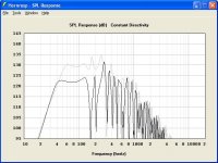
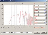
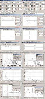
Here is an overlay between the ss15 (63v) and the T-qwp(47.7v) The advantage (obviously) to the quarter wave pipe is being able to set your high pass lower. However armed with a 32hz@24db highpass on the ss15 to keep excursion in check, the difference in 35hz output is not dramatic.
thanks don.
Thanks for this, but I know I've modeled quarter wave pipes, and never came up with anything that really helped me out in the PA department.
Here is an overlay between the ss15 (63v) and the T-qwp(47.7v) The advantage (obviously) to the quarter wave pipe is being able to set your high pass lower. However armed with a 32hz@24db highpass on the ss15 to keep excursion in check, the difference in 35hz output is not dramatic.
thanks don.
Attachments
Bjorno: Thanks for the help, I'll need it!
Michael: There are many ways of making a box with a clean edge. The cut pattern I included is intended to leave the left and right side pieces protruding
on the top, rear and bottom. Next, it's router time. Using a bit with a ball- bearing pilot, trim the protruding edges. Then, switch to a 1/4" round-over bit
and you've got an edge that looks perfect.
Brian: You've had some interesting ideas in the past. Thanks for your help. This thing is still a work in progress, and any help you can give is welcome.
Jim: Your SS15 is still #1, but you can't fault me for trying. This, a pair of 8" speakers and a Crown XTI would make an interesting 6-string bass unit.
Salzburg: Moving the mouth 90 degrees shouldn't cause any problems.
This box ain't quite there ... but it is interesting!
Last edited:
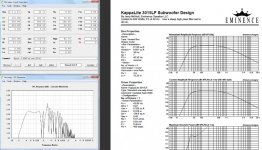
Don,If you gotta have lower and you're willing to give up a little loudness, have I got a sub for you!!! Made from a single sheet of 4'x8'x15mm (or 5/8") ply, it
should be a quick and easy build for those who must have 35Hz in singles. Bjorno calls it a T-QWP (Tapped Quarter Wave Pipe).
It may need a little dacron or foam, and maybe a reflector or two, to tame the resonances. I'd try to HP @ 30Hz 24dB/oct and X-O @ 120Hz 24dB/oct
A ported box with a 3015LF can play louder and lower than the TQWP, and uses less wood to build.
The BR will have much smoother upper response, and rolls off a bit less steep below Fb.
The BR will time align at crossover without requiring delay.
Art Welter
Attachments
Here is an overlay between the ss15 (63v) and the T-qwp(47.7v) The advantage (obviously) to the quarter wave pipe is being able to set your high pass lower.
It's also doing the same 35 Hz level with a lot less watts.
Don,Bjorno: Thanks for the help, I'll need it!
This, a pair of 8" speakers and a Crown XTI would make an interesting 6-string bass unit.
This box ain't quite there ... but it is interesting!
The low "B" on a bass is about 31 Hz.
Your TQWP is already on the uphill swing of a rapid excursion increase above 40 Hz (low E on a 4 string bass).
It will do OK for the upper harmonics of the low bass notes, but the speaker will flap if you push the fundamentals.
Art
Attachments
Hi Art : It's hard to get ANY fundamental on an electric bass. Everything seems to be working against you. Most bass speakers have nothing below
60Hz, and the pickup is mounted at less than 20% of string length.
On the open "E" the original Fender P-Bass fundamental was down -10dB from the 2nd harmonic !
60Hz, and the pickup is mounted at less than 20% of string length.
On the open "E" the original Fender P-Bass fundamental was down -10dB from the 2nd harmonic !
Last edited:
That's true, and why most recordings of electric bass use direct boxes so the fundamentals can be captured.Hi Art : It's hard to get ANY fundamental on an electric bass. Everything seems to be working against you. Most bass speakers have nothing below
60Hz, and the pickup is mounted at less than 20% of string length.
The original P-Bass fundamental was down -10dB from the 2nd harmonic!
The Fender P-bass is similar in harmonic structure to an upright bass.
There are other basses with far more LF output.
A slapped/plucked four string Yamaha puts out an energy spectrum that looks flat to near DC.
For PA, I almost always mic the bass amp speaker for the player's "sound", but use a direct box to get what the pickup is actually picking up.
The dual Lab 12 ported design I use, and the Keystone tapped horn I will now be using, both are capable with a little EQ of flat response down to the low B string frequency with low distortion.
Art
Bjorno: Thanks for the help, I'll need it!/QUOTE]
Hi Don,
Maybe I promised too much,but I been to busy....I will continue to post what I promised later...
I just made one picture so far to spread some light why the T-QWP is a good bass harnessing alternative to other designs using similar size of cabinet volume.
I've also attached a picture showing what I been using so far (> 30 years), as a norm for 'blameless' gldy (complying with what I believe return Hi-Fi SQ) to take a look at.
b🙂
Attachments
Brian: You've had some interesting ideas in the past. Thanks for your help. This thing is still a work in progress, and any help you can give is welcome.
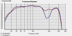
Attached is the frequency response of my POC TP before (in blue) and after (in red) a "dogfood duct" modification was applied. Note: this isn't optimized by any means - I just cut a panel a bit smaller than the cross-section of the pipe, then adjusted its position in the pipe until the notch was filled in.
The DD mod results in a shallower rolloff at the low end, and about 2dB less output at 50 Hz. However subectively it sounds quite a bit better than the un-modded TP. It basically sounds like a big sealed box, with a cutoff point a lot lower than what you'd expect with this driver.
BTW - I think I've found a way to sim the DD-mod with TPs in HornResp. Going to try it later tonight to see if it works. Alas, the dishes are calling, so fiddling around in HornResp will have to wait 🙂
Attachments
BTW - I think I've found a way to sim the DD-mod with TPs in HornResp. Going to try it later tonight to see if it works. Alas, the dishes are calling, so fiddling around in HornResp will have to wait 🙂
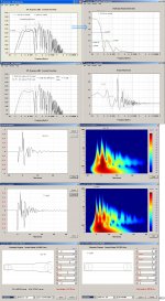
Hmm.. it nah wukky. Someone please tell me where I'm going wrong.
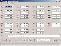
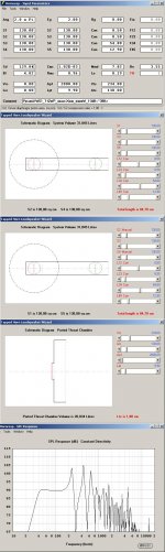
1. Start with the HornResp input data seen below in the first image. That data basically describes my POC TP, without the DD modification. System volume works out to be 51.9 litres, according to HornResp. Total pipe length = 179 cm.
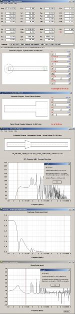
2. Now, let's put in the DD. This is basically a 1.8 cm thick panel that restricts the cross-section of the pipe down to 40 cm. It is placed about 90 cm from the mouth. To do this, set L12 to 0.1 and L23 to 77.1.
Now, we're going to simulate the DD and the balance of the pipe (179 - 77.1 - 1.8 = 100.1 cm) by using Vtc, Atc, Ap1 and Lp1.
3. Using the "Chamber" option, set Atc to 290 cm and then adjust Vtc until Ltc reaches 100.1 cm.
4. Finally, insert the DD by setting Ap1 to 40 cm and Lpt to 1.8 cm.
Now, this should produce an FR similar to what I've measured, but it doesn't. The notch is reduced, but still very present. The change at the lower cutoff point does seem to be consistent with what I've measured though. HornResp is also saying that net volume also seems to have increased, to 55.23 litres, when theoretically it should have reduced, if anything.
So, the question now is who's wrong - me or HornResp 🙂.
Attachments
Brian,
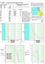
To cure(move up) the first dip, you need an acoustical LP filter in front of the driver.
Have a look at this:
b🙂
Thanks Bjorno, but what I'm really trying to figure out here is why the HornResp predictions doesn't match the measured results for the DFD modification. The schematic looks identical to the actual physical layout of the subwoofer, but the notch isn't filled in anywhere near as much in the predicted response as what I'm observing via measurement.
It's possible that I measured its placement along the pipe wrong. I'm going to measure it again this morning. The response change introduced by the DFD mod is VERY sensitive to placement - if I literally move it an inch back or forth, the notch reappears, albeit a bit smaller. But even then, when I sim this in HornResp, the peak and notch given in the predictions does not show up in my measurements.
Brian,
I too wonder why your practical result doesn't comply with HR., maybe the HR air model isn't safe when your DFD is placed close to the throat area segment?
Maybe we should invite David McBean to have a look at this?
Hints here ?:
Acoustic Flow Duct Analysis
b🙂
I too wonder why your practical result doesn't comply with HR., maybe the HR air model isn't safe when your DFD is placed close to the throat area segment?
Maybe we should invite David McBean to have a look at this?
Hints here ?:
Acoustic Flow Duct Analysis
b🙂
Hmm.. it nah wukky. Someone please tell me where I'm going wrong.
1. Start with the HornResp input data seen below in the first image. That data basically describes my POC TP, without the DD modification. System volume works out to be 51.9 litres, according to HornResp. Total pipe length = 179 cm.
2. Now, let's put in the DD. This is basically a 1.8 cm thick panel that restricts the cross-section of the pipe down to 40 cm. It is placed about 90 cm from the mouth. To do this, set L12 to 0.1 and L23 to 77.1.
Now, we're going to simulate the DD and the balance of the pipe (179 - 77.1 - 1.8 = 100.1 cm) by using Vtc, Atc, Ap1 and Lp1.
3. Using the "Chamber" option, set Atc to 290 cm and then adjust Vtc until Ltc reaches 100.1 cm.
4. Finally, insert the DD by setting Ap1 to 40 cm and Lpt to 1.8 cm.
Now, this should produce an FR similar to what I've measured, but it doesn't. The notch is reduced, but still very present. The change at the lower cutoff point does seem to be consistent with what I've measured though. HornResp is also saying that net volume also seems to have increased, to 55.23 litres, when theoretically it should have reduced, if anything.
So, the question now is who's wrong - me or HornResp 🙂.
Hi Brian,
In this particular case, I don't think it is Hornresp that is wrong... 🙂.
In attempting to insert a constriction 90 cm from the mouth, you have actually changed the tapped horn system configuration quite significantly. In the original design the throat side of the diaphragm is offset 11 cm from the closed end S1. In your modified design the throat side of the diaphragm is no longer offset along the horn - it faces directly into the 100.1 cm long throat chamber, which you are using to form part of the horn.
The original design has a pipe length of 11 + 155.1 + 12.9 = 179 cm, which when multiplied by the constant cross-sectional area of 290 sq cm gives a volume of 51.91 litres.
The modified design has a pipe length of 100.1 + 1.8 + 0.1 + 77.1 + 12.9 = 192 cm. The volume in this case is given by (290 x (100.1 + 0.1 + 77.1 + 12.9)) + (1.8 x 40) = 55.23 litres.
I think that you might be using Hornresp to try to compare an "apple" with an "orange" 🙂.
The 1.8 cm long constriction could of course be modelled in AkAbak quite easily, while still retaining the correct tapped horn configuration.
Kind regards,
David
Last edited:
- Status
- Not open for further replies.
- Home
- Loudspeakers
- Subwoofers
- Single Sheet Challenge (with bass) !!!