Supplies are linear, bipolar, just bridge and capacitors - should provide plenty of energy to explode a chip amp here or there..😱
BTDT
First attempt at this I used an old IE core trafo which had, unbeknownst to me at the time, a quite high magnetisation current requirement. This let the smoke out of a pair of LM1875s about three milliseconds after turn on and peppered the lab wall with shrapnel.
My Simon Yorke uses the ILP HY-60 module which is 60 watts which is what made me think a LM3886 would be a more modern replacement.
I too would have thought that a toroid would be ideal and indeed used one with a 1kW set up using a Bose 1800 power amplifier 15yrs ago, no problems..
I expect I may have to modify those cheap amp boards to incorporate a reasonable mute delay.
I got for my own turntable supplys reliable results with ringcore transformers and class D poweramps !
See also http://www.lencoheaven.net/forum/index.php?topic=13981.0
Volken
BTDT
First attempt at this I used an old IE core trafo which had, unbeknownst to me at the time, a quite high magnetisation current requirement. This let the smoke out of a pair of LM1875s about three milliseconds after turn on and peppered the lab wall with shrapnel.
I think I will wear safety glasses when I first power this thing up.
😀
A discrete power amp with built in electronic current limiting is not beyond the realm of possibility.
I think that such a system could benefit from a fine-tuning vernier: it could be used to compensate for various sources of inaccuracies in the slip percentage and mechanical transmission for example.
I have already examined the possibility of such a vernier on a digital generation chain (for other purposes but the principles remain identical).
Basically, I see two promising paths, both based on the offset-PLL principle: one rather conventional, except the frequency subtractor and phase comparator would be digital, and the other using a F/V converter to servo the difference frequency to an analogue voltage.
Both options would give a convenient, deterministic and accurate means of varying the output frequency, by say +/-0.5% full range.
I will try to come up with such an add-on circuit when I find some time (and inspiration)
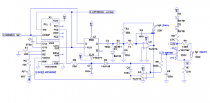
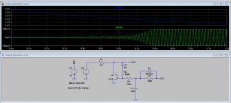
I have tested the Frequency-Vernier concept on a prototype.
I have opted for the V/F option, since it seems better suited in this case.
The reference and output frequencies are compared by a D-type FF wired as a frequency subtractor: U1.
The resulting frequency is then converted to a voltage by the FVC built around D1, D2 and U2.
The output voltage is then compared to the offset value coming from the vernier potentiometer, and sent to the input of the VCO to servo the output frequency.
In this case, I have chosen to make the output frequency lower than the reference. Both options are possible, but since 2.5MHz crystals are commonly available (or the frequency can be derived from a 5, 10 or 20MHz crystal), this one was chosen.
A common problem with (small-) offset loops is that they can lock to the difference or sum frequency. Here, with the FLL, the problem is slightly different, but it exists nevertheless: the simple frequency subtractor generate the absolute value of the difference, and makes no difference whether the output is higher or lower than the reference frequency.
If the loop attempts to lock to the higher frequencies, the servo loop has its sign reversed and the frequency is instantly locked up at the maximum frequency permitted by the VCO components.
In order to recover from/avoid such a situation, the phase comparator II of the 4046 is used as a frequency comparator: when the sign is wrong, it generates a high level and forces the loop to return to a normal situation via D5.
There are many possibilities to implement that function, and with hindsight this one is probably not optimal, but it does work: although the circuit wasn't naturally prone to lock-up (it always started correctly without the anti lock-up connection), it was able to restore the normal operation after a manually forced lock-up.
For example, a set or reset input of the flip-flop could be used to disable the FVC with a low level of the comparator (signal and comp inputs reversed).
No attempt has been made to optimize the circuit, it is just a proof of concept, and the loop parameters in particular could benefit from a good dimensioning: I just threw reasonable values in, and it worked, but it is certainly possible to improve matters.
However, it would be perfectly usable, even in its present condition: it is stable, nice and well-behaved
The stability and accuracy will depend mainly on the FVC components, and it isn't difficult to select stable and accurate ones in this range.
The circuit has been dimensioned for a +/-1% adjustment range, but other values would be easy to implement
Next I will go into practical considerations and show some pics of the prototype.
Attachments
A word of the control strategy:
Here, the loop is of the offset-zero variety, ie the "center" frequency is not that of the reference
I have chosen this option for two reasons: one is the simplicity of the frequency subtractor, but the most important one has to do with practicalities: in a zero-offset system, when the frequency shift is small, the two frequencies are very close to each other, obviously
This can be problematic, because the 4046 oscillator will tend to synchronize to a signal in physical proximity, just by itself and not requiring any action from the VCO input signal.
This means that a "dead-band" will exist around the zero, and the width of that deadband will depend on how well the VCO is shielded from parasitic external influences.
I had first attempted to build my prototype on a breadboard, and this proved to be a real issue.
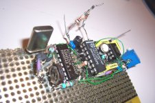
With the current prototype built on a shielded perf-board, and no IC socket for the 4046, the problem is not detectable anymore, even with a minimal offset; anyway, with the offset-zero method, the two frequencies always stay well clear from each other.
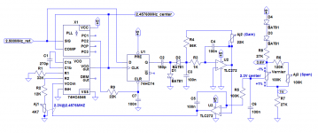
Here is how the circuit is supposed to be adjusted:
- Remove the TLC272 from its socket, and apply 2.3V to the VCO input. Tune Aj1 to read 2.4576 MHz on the VCO output.
- With U2/3 back in place, adjust Aj3 to read 2.3V between the top and bottom terminals of the vernier potentiometer
- Center accurately the vernier pot (2.3V on the wiper), and adjust the gain of the FVC (Aj2) to get a 2.457600MHz output.
That's it: now the circuit is fully calibrated, with the nominal frequency at the pot center and exactly +/-1% at the end stops.
Some kind of indication could be provided, either by digitally generating the tuning voltage, or by connecting a suitably scaled voltmeter between the output of U2 and a resistive divider having a 2.3V output.
A note on the components:
The HC versions of the 4046 exist in many tastes and variants, mostly incompatible regarding the values of the tuning components and sometimes the pinout. The one that was used here is the Philips (NXP) PC74HCT4046AP.
If you use another type, you will need to adapt the component values of the VCO.
I have used a TLC272 for the opamp, but many others would be suitable, including probably the LM358. I will test this one of these days.
As I said, the circuit is just a proof-of-concept, and can be optimized or implemented in other ways. It is a good starting point though, because it works and validates the principles, but the details may vary widely.
A more "luxurious" FVC could be used for instance, as it is the most important building block regarding accuracy and stability.
Why use such an hybrid digital/analog scheme for frequency synthesis, when a fully digital method could be (slightly) simpler and have an arbitrarily high accuracy?
I think it brings the best of both worlds, namely the stability of a crystal-controlled digital circuit and the infinite resolution of analog, without the inherent jitter caused by the granularity of the primary clock that is inevitable in a purely digital scheme.
It is probably applicable to other problems, in particular test instruments, where an accurate frequency needs to be tweaked by a small and deterministic amount without degrading the initial performances.
It is also simple and inexpensive and uses only commodity components
Here, the loop is of the offset-zero variety, ie the "center" frequency is not that of the reference
I have chosen this option for two reasons: one is the simplicity of the frequency subtractor, but the most important one has to do with practicalities: in a zero-offset system, when the frequency shift is small, the two frequencies are very close to each other, obviously
This can be problematic, because the 4046 oscillator will tend to synchronize to a signal in physical proximity, just by itself and not requiring any action from the VCO input signal.
This means that a "dead-band" will exist around the zero, and the width of that deadband will depend on how well the VCO is shielded from parasitic external influences.
I had first attempted to build my prototype on a breadboard, and this proved to be a real issue.
With the current prototype built on a shielded perf-board, and no IC socket for the 4046, the problem is not detectable anymore, even with a minimal offset; anyway, with the offset-zero method, the two frequencies always stay well clear from each other.
Here is how the circuit is supposed to be adjusted:
- Remove the TLC272 from its socket, and apply 2.3V to the VCO input. Tune Aj1 to read 2.4576 MHz on the VCO output.
- With U2/3 back in place, adjust Aj3 to read 2.3V between the top and bottom terminals of the vernier potentiometer
- Center accurately the vernier pot (2.3V on the wiper), and adjust the gain of the FVC (Aj2) to get a 2.457600MHz output.
That's it: now the circuit is fully calibrated, with the nominal frequency at the pot center and exactly +/-1% at the end stops.
Some kind of indication could be provided, either by digitally generating the tuning voltage, or by connecting a suitably scaled voltmeter between the output of U2 and a resistive divider having a 2.3V output.
A note on the components:
The HC versions of the 4046 exist in many tastes and variants, mostly incompatible regarding the values of the tuning components and sometimes the pinout. The one that was used here is the Philips (NXP) PC74HCT4046AP.
If you use another type, you will need to adapt the component values of the VCO.
I have used a TLC272 for the opamp, but many others would be suitable, including probably the LM358. I will test this one of these days.
As I said, the circuit is just a proof-of-concept, and can be optimized or implemented in other ways. It is a good starting point though, because it works and validates the principles, but the details may vary widely.
A more "luxurious" FVC could be used for instance, as it is the most important building block regarding accuracy and stability.
Why use such an hybrid digital/analog scheme for frequency synthesis, when a fully digital method could be (slightly) simpler and have an arbitrarily high accuracy?
I think it brings the best of both worlds, namely the stability of a crystal-controlled digital circuit and the infinite resolution of analog, without the inherent jitter caused by the granularity of the primary clock that is inevitable in a purely digital scheme.
It is probably applicable to other problems, in particular test instruments, where an accurate frequency needs to be tweaked by a small and deterministic amount without degrading the initial performances.
It is also simple and inexpensive and uses only commodity components
Attachments
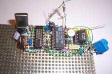
I have just tested the alternate anti lock-up scheme: it works too.
Here it is, I think it is preferable to the previous one.
By the way, in the #25, I mistakenly talked of V/F and VFC: it is F/V and FVC, of course. Could a moderator rectify this? Thanks
Here it is, I think it is preferable to the previous one.
By the way, in the #25, I mistakenly talked of V/F and VFC: it is F/V and FVC, of course. Could a moderator rectify this? Thanks
Attachments
Hi Elvee,
I corrected the references you mentioned, please make sure I didn't miss any, and send me a PM if I did.. 😀
Very clever circuit design, I'm thinking something on the order of +/-3% adjustment range would be typical if one was looking to disable or ignore the eddy current brake, or did you intend this more as fine tuning while retaining the original brake? It may be simple as a few minor resistor value tweaks in the span/vernier circuit.
Pure fine-tuning without mods to the existing hardware was my initial intention, but of course getting rid completely of the brake will reduce the temperature dependency of the brake, and will result in a more stable speed so that is a valid option.Very clever circuit design, I'm thinking something on the order of +/-3% adjustment range would be typical if one was looking to disable or ignore the eddy current brake, or did you intend this more as fine tuning while retaining the original brake?
Yes, basically the range can be increased by reducing the gain of the FVC: dividing C3 or R4's value by three will result in a span of +/- 3%, but of course with these values and without other corrections, the new center frequency will be lower than 2.4576MHz.It may be simple as a few minor resistor value tweaks in the span/vernier circuit.
The solution is to use a slightly higher frequency crystal: 2.56MHz is also a common value, and it could theoretically give more than +/-4% span, but of course it isn't a good idea to flirt with the limits, and for 3% it isn't necessary, so it would be OK.
The cost of increasing the adjustment range (of course, there are no free lunches, etc...) will be that a larger proportion of the output frequency will depend on the analog fine-tuning rather than the crystal, but since the proportion remains small, the effect won't be catastrophic: if one uses a very crude FVC with carbon resistors and an ordinary charge pump cap, the stability can be expected to be of the order of 1%. 1% of 3% is still only 0.03%, not really bad, and achieving 0.1% stability only requires common metal film resistors and COG, PP or mylar caps.
With reasonably good components in the charge pump and vernier divider and a stable supply, an end stability of 0.005% is certainly achievable, and this will be a worst case, at the end of the adjustment range.
Last edited:
The 15V x 2 triad power transformer I ordered a few days ago got here yesterday, the chassis arrived a few days ago.. I'm ready to start assembling and testing the source. I have few ideas that I hope will allow the LM3886 to live.
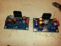
I had originally just planned on one amplifier, but given load current and dissipation decided paralleling a second amp could hardly hurt.
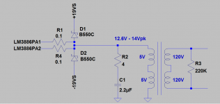
I have added schottky clamp diodes across the output of the amplifiers, and had originally planned on a current limiting resistor between them and the transformer but concluded that the effect on regulation and source impedance would not be good. I'm placing a zobel on the primary in order to reduce the effect of the inductive load on the amps at high frequencies (stability margin) and a resistor on the secondary to prevent them from being completely unloaded during motor switching - a zobel may be required here too.
I had originally just planned on one amplifier, but given load current and dissipation decided paralleling a second amp could hardly hurt.
I have added schottky clamp diodes across the output of the amplifiers, and had originally planned on a current limiting resistor between them and the transformer but concluded that the effect on regulation and source impedance would not be good. I'm placing a zobel on the primary in order to reduce the effect of the inductive load on the amps at high frequencies (stability margin) and a resistor on the secondary to prevent them from being completely unloaded during motor switching - a zobel may be required here too.
Attachments
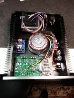
Build Picture (Complete with Mistakes)
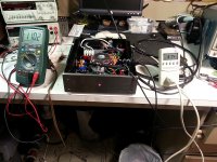
Here it is, tomorrow I will wire everything up and "test" it. The finish on this box is amazingly fragile, but it really doesn't matter since it will be on the floor somewhere where it will just get trashed anyway.
My one regret is that the rectifier is mounted a bit close to the source board, worst case if EMI proves to be a problem I will flip the heat sink and re-orient the power amplifier on that side.
Frankly it is a bit tight, had I realized what a project it would be to shoehorn all of this in there I would have gotten a slightly larger box. Some things are going to get quite warm in operation which is why I wanted something with a fair amount of heat sink.
Attachments
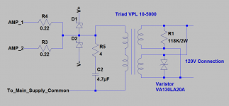
In talking to several people I have determined that I need to take extra precautions to keep the LM3886 alive in this application so I have made some further revisions to the output protection circuit and will be adding a simple JFET based shunt attenuator to ramp up the sine wave drive after a couple of seconds.. Attached is the revised schematic for the protection circuitry.
Attachments

In order to avoid the risk of exceeding the V*s product of the transformer due to start-up and DC for example, I would connect the center-tap of the power transformer to the capacitor's mid-point through a resistor of a few ohms.
The effect on normal operation will be small, but if a sequence of events leads to the saturation of the core, the resistor will act as a ballast.
There is also one thing to keep in mind: when a transformer is used backwards, the regulation works in the wrong direction: the actual transformation ratio is not 240/10V, but smaller, and when the primary (the new secondary) is loaded, there will also be a drop under load.
If some unused winding is still present, it would be a good idea to add it to the 240V secondary.
Definitely aware of the issues of using a typical power transformer as a step up, I choose an EI core type to reduce the bad behavior during start up based on the experience of several people I know who blazed this trail ahead of me. I expect to have to adjust the drive voltage to compensate for the winding DCR under load. In the case of the TD-124 my target supply voltage is only 110V.
I will be adding a simple little circuit to ramp up the drive to the amplifiers over a period of a second or so. I've gone to some lengths to avoid DC at start up, but ended up with an offset induced by the internal asymmetry of the 74HC series logic I used to generate the 50 / 60Hz squarewave to the LPF. I am using offset nulling to take care of most of it, in order to minimize DC at the output of the amplifier due to coupling cap charging currents.
I will be adding a simple little circuit to ramp up the drive to the amplifiers over a period of a second or so. I've gone to some lengths to avoid DC at start up, but ended up with an offset induced by the internal asymmetry of the 74HC series logic I used to generate the 50 / 60Hz squarewave to the LPF. I am using offset nulling to take care of most of it, in order to minimize DC at the output of the amplifier due to coupling cap charging currents.
Unit is fully operational: Scattered details follow
I finally put the whole thing together over the past week. Here are some details:
Two amplifiers are used in parallel and driven by the J111 based softstart. The amplifiers drive a protection board comprising a zobel network, a pair of high current schottky diodes, and a pair of resistors to sum the amp outputs.
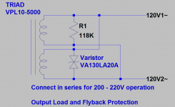
The output of the transformer is permanently connected to a V130LA20A varistor on one high voltage secondary and a 118K 2W resistor on the other. The secondaries may be connected in series or parallel for 100 - 115V and 200 - 230V at 50Hz or 60Hz. If higher voltages are required I recommend a slightly higher voltage toroid rather than the 15V+15V unit I used.
The soft start is driven directly by the LPF which in turn is driven by the output oscillator I designed to replace the ELM chips I originally planned on using, but which proved to be less accurate than I was comfortable with.
The unit is designed to power up safely with no load connected, and will start a TD-124 without difficulty.. The voltage under load must be set due to winding DCR some sag is expected. Power consumption is 37W when driving a 15W load. Note this is intended for driving turntable motors of up to roughly 25W only, 50Hz or 60Hz is available just by setting the jumpers appropriately.
I finally put the whole thing together over the past week. Here are some details:
- Added simple soft start to ramp up the sine wave drive to the power amplifiers after they unmute. Power is picked up from the negative 12V regulator on the LPF board.
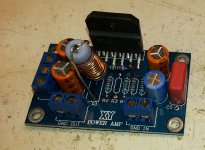
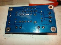
- Extensively modified the inexpensive XY amplifier module kits purchased on eBay so that they do not oscillate when loaded. Note that the pictures of the amplifier rework do not show C3 the 18pF capacitor required for stability. The stock muting component values are retained. Note etch cuts!
Two amplifiers are used in parallel and driven by the J111 based softstart. The amplifiers drive a protection board comprising a zobel network, a pair of high current schottky diodes, and a pair of resistors to sum the amp outputs.
The output of the transformer is permanently connected to a V130LA20A varistor on one high voltage secondary and a 118K 2W resistor on the other. The secondaries may be connected in series or parallel for 100 - 115V and 200 - 230V at 50Hz or 60Hz. If higher voltages are required I recommend a slightly higher voltage toroid rather than the 15V+15V unit I used.
The soft start is driven directly by the LPF which in turn is driven by the output oscillator I designed to replace the ELM chips I originally planned on using, but which proved to be less accurate than I was comfortable with.
The unit is designed to power up safely with no load connected, and will start a TD-124 without difficulty.. The voltage under load must be set due to winding DCR some sag is expected. Power consumption is 37W when driving a 15W load. Note this is intended for driving turntable motors of up to roughly 25W only, 50Hz or 60Hz is available just by setting the jumpers appropriately.
Attachments
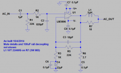

Here is some more information. I've attached schematics for the LPF and the source oscillator. If you stick with 74HC cmos be aware that there is some offset and it will need to be trimmed by connecting a 1M - 2.21M resistor from -12V to U6-2 in the first stage of the LPF. Exact value found by trial and error, but IIRC I am using a 2.21M resistor which my case nulled the offset.
Also here is a new schematic for the protection board..
Output transformer is a Triad VPL10-5000 EI
Power transformer is a Triad VPT30-3330 Toroid
Both are available from Digi-Key as are most all of the other parts.
Also here is a new schematic for the protection board..
Output transformer is a Triad VPL10-5000 EI
Power transformer is a Triad VPT30-3330 Toroid
Both are available from Digi-Key as are most all of the other parts.
Attachments
Reworking XY Amp so that they live.
These amp modules are available from several sellers and are silk screened XY Power Amp. They come with all parts required to assemble; except that they don't.
Best to work in an ESD controlled environment if possible.
You will need the following parts:
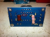
Two 10R 5% 3W metal oxide resistor, diameter ~ 10mm, you will wind 10 turns of 22 awg magnet wire on this to make the thiele network. (Parallel R L)
Two 2.7R 5% 2W MO for the zobel network (boucherot cell)
Two 820 - 2200pF mica
Eight 0.1uF X7R 100V 1206 SMD ceramic capacitors
Two 18 - 22pF 100V COG ceramic capacitors.
Prior to assembly perform the following etch cuts:
Assembly:
Normally I would recommend installing the chip last, but since one of the modifications involves soldering a cap and resistor to leads that will be less accessible with the board assembled.
Note that this might in some sense be overkill, but unmodified they oscillate quite nicely with the transformer connected. I wanted to make sure they were stable and would survive minor accidents and unpredictable loads.
These amp modules are available from several sellers and are silk screened XY Power Amp. They come with all parts required to assemble; except that they don't.
Best to work in an ESD controlled environment if possible.
You will need the following parts:
Two 10R 5% 3W metal oxide resistor, diameter ~ 10mm, you will wind 10 turns of 22 awg magnet wire on this to make the thiele network. (Parallel R L)
Two 2.7R 5% 2W MO for the zobel network (boucherot cell)
Two 820 - 2200pF mica
Eight 0.1uF X7R 100V 1206 SMD ceramic capacitors
Two 18 - 22pF 100V COG ceramic capacitors.
Prior to assembly perform the following etch cuts:
- Topside cut the etch between R1 and R3
- Bottom side cut etch between R3 and R4
- Solder one end of 22AWG magnet wire snug to the body of the 10R resistor.
- Wind 16 turns of magnet wire on the 10R resistor. (edit)
- Solder other end snug to body
Assembly:
Normally I would recommend installing the chip last, but since one of the modifications involves soldering a cap and resistor to leads that will be less accessible with the board assembled.
- Install LM3886TF and solder.
- Solder one 22K resistor furnished in the kit directly between pins 3 (output) and 9 (-IN) on the top side. Keep the body slightly off of the board.
- Solder one 18 - 22pF COG cap to the same points mentioned above. Keep all leads short, and check for shorts (Note this cap is not pictured but should be installed directly on top of the 22K resistor.
- Install all remaining parts provided with the kit except R1. R3 location should be empty.
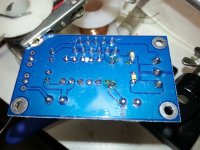
- Referring to the bottom side photographs below install the four 0.1uF and 820 - 2200pF mica as shown.
- Do not install the 2.7R resistor for the zobel network
- Install the thiele network in location of R1 and solder, leave 5mm of lead on bottom side close to body of chip.
- As shown in bottom side rework photo form the 2.7R resistor leads and solder to the 5mm of lead from the previous step and the unsoldered end of the 0.1uF ceramic cap.
Note that this might in some sense be overkill, but unmodified they oscillate quite nicely with the transformer connected. I wanted to make sure they were stable and would survive minor accidents and unpredictable loads.
Attachments

The turntable this unit is powering is a TD-124 original series with an intermediate version of the E50 motor.
Power consumption is as follows:
120mA @ 110Vrms, 60Hz
Real power: 9.1W
Apparent power: 14.1VA
Power Factor: 0.65
The source consumes 37.1W or 51VA @ 119V which is towards the higher end of the voltage range here.
Power consumption is as follows:
120mA @ 110Vrms, 60Hz
Real power: 9.1W
Apparent power: 14.1VA
Power Factor: 0.65
The source consumes 37.1W or 51VA @ 119V which is towards the higher end of the voltage range here.
Hi, Kevinkr can you make any comments on how well your new power source unit works with your TD-124 and what differences ( if any) you have noticed with turntable playback. I assume the stability of the new power source unit is satisfactory for your needs?
Thanks
Frank M
Thanks
Frank M
- Status
- Not open for further replies.
- Home
- Source & Line
- Analogue Source
- Single Phase Power Source (AC Regenerator) for Induction Motor Powered Turntables