Hi
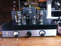
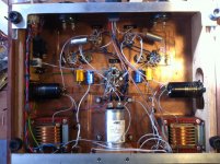
I used the chassis and ironwork from an earlier build 6B4G amp to get a more powerfull and integrated KT88. Testing the new amp I really miss power. I do have to turn the volume to max to get the about the power of my laptop !
Anyone any idea what goes wrong ? Or do I have to swap the 6SN7 tubes for 6SL7 with much more gain.
Thanx for your help
Attachments
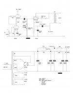
I think there is a mistake in the PSU. To drop 115V with 1K8 resistor your SRPP should work at about 64 mA anode current!!
Just to give you some ideas.....I would not go for the 6SL7, I would rather use the 6SN7 sections as single ended common cathode stages in cascade (DC coupled) in a similar way to the Sun Audio design. Having more than 400V supply you can play with this a lot. You can bypass the cathode of first or the second stage, both cathodes or none them to get the right gain and more imprtantly the right drive! As you are RC coupling to the KT88 you might also try a CCS plate load for the second stage and find its load by tweaking the KT88 grid resistor. Having the two stages DC coupled you might get very low distortion because of cancellation with some tuning. Then most of THD would be that of the KT88. You might also by-pass both capacitors and use some feedback.
You might also use the two 6SN7 sections as RC coupled voltage amplifiers if you want to make it simple. I think you have many options to try before swapping the 6SN7 with the 6SL7 and the SRPP is your main limitation.
Using about 1K for decoupling the supply you should be able to get 400V for the the 6SN7.
Last edited:
One other thing which is not good in your schematic is the heater supply. There is no reference to groun. However even in this case, using SRPP or DC coupled stages, you need to lift the reference voltage for the heater of the upper tube. You can use one tube shared between the two channels as the lower valve and the other as upper tube in the same way.
The 6SN7 has a max rating of 100V DC heater-to-cathode voltage (twice this value for DC + peak). The 6SL7 a bit less. So, even with 300V supply you are way above max ratings with the SRPP for sure. The result will be that the heater-to-cathode insulation will fail suddenly. This will be the first limitation for the tube life. A compromise could be that you lift the single heater supply you have to a voltage midway between the upper and lower cathode voltages (for example, the heater supply is not grounded but is connected to a reference voltage of 80V if your SRPP is working at 300V where the lower cathode is few volts above ground and the upper cathode at about 160V). You can create the reference voltage from the anode supply using two or more sistors in series after the last capacitor and bypass the 80V rail with a small capacitor. You only need little current (1 mA should be enough) through the series of resistors.
The 6SN7 has a max rating of 100V DC heater-to-cathode voltage (twice this value for DC + peak). The 6SL7 a bit less. So, even with 300V supply you are way above max ratings with the SRPP for sure. The result will be that the heater-to-cathode insulation will fail suddenly. This will be the first limitation for the tube life. A compromise could be that you lift the single heater supply you have to a voltage midway between the upper and lower cathode voltages (for example, the heater supply is not grounded but is connected to a reference voltage of 80V if your SRPP is working at 300V where the lower cathode is few volts above ground and the upper cathode at about 160V). You can create the reference voltage from the anode supply using two or more sistors in series after the last capacitor and bypass the 80V rail with a small capacitor. You only need little current (1 mA should be enough) through the series of resistors.
Last edited:
If you don't want to reinvent the wheel.
An externally hosted image should be here but it was not working when we last tested it.
Hi 45
Thanx for your reply
The 1k8 in the power-suply was already replaced by 46K.
I did some homework and changes the schematics
Do you think this will work beter ??
The second tube will work at lower current than the first in your schematic. I would change that 22K resistor in the supply. You could use another choke, in case.
For example, in a similar way to the schematic posted above, if you have 405V for B++ you can use:
1) input tube -> 750R for the cathode and 75K for the anode
2) second tube -> 22K for both cathode and anode.
This way the first tube will work at about 4 mA with 3V bias and second at about 5 mA with about 6V bias.
You might try 75V anode voltage for the first tube with low bias, as in your schematic, but you should increase the current in the second with enough bias. I have never tried such low voltage (and bias) with the 6SN7.
You still need to lift the heater to a reference voltage midway between the two cathodes. In the example above the first cathode is at +3V and the second at about 116V. So the heather should be at about 56-57V. It could be a bit higher because the second tube will swing more voltage. To do this from B++ =405V you put 330K + 75K to ground. This will give 1mA current and you will get 75V in between the two resistors and this will be the reference voltage for the heater. Bypass the 75K resistor with a small capacitor.
Last edited:
To answer your original question, I would look at your overall gain first.
6SN7 - mu = 20
KT88 - mu = 8
5K:8r transformer gives 25:1 step down ratio
So the total system gain is on the order of:
(20*8)/25 = 6.4
It's not that you don't have enough power, you don't have enough gain to get the power out for the level of input signal you are driving it with.
Your options are (1) add a preamp, or (2) redesign the front end to get more gain.
The suggestions have been for option 2.
If you are going to direct couple the two gain stages, be sure to re-calculate Pd of the cathode resistor in the second stage.
Increasing the anode resistor as 45 proposes will serve several purposes including reducing distortion, increasing gain, and reducing power dissipation in the cathode resistor as well as the anode resistor. (warning, run-on sentence)
What are you driving it with? if you use the headphone out of your iPod as a source, then the gain of your front end is insufficient. A CD player on the other hand should be capable of driving your amp to full power.
Yes, it looks ok. One more thing, increase the by-pass capacitor for the second 6SN7. However you can do this when you build the amp....
Now you only need to use resistors of appropriate power, especially the 75K anode resistor. This will see about 4 mA and thus will dissipate 1.2 W.
You can use 5W carbon film resistors (Kiwame or KOA SPR, depending on where you are...) and you can also get 75K using two 150K resistors in parallel.
P.S.
Are you sure about the 390R cathode resistor for the KT88?
Last edited:
A CD player on the other hand should be capable of driving your amp to full power.
A 6SN7 SRPP can provide a gain around 16-17 only. That means you need more than 1.6 Vrms.
Thanx for helping me all 🙂
following 45's usefull remarks, the final scheme should look like this ?
1K8 resistors at the RC filters will drop 18V for one channel and about 16V for the other as the currents are 10 and 9 mA, respectively. If you want at least 405V from 415V that resistor needs to be 1K.
A CD player gives you 2 V RMS.A 6SN7 SRPP can provide a gain around 16-17 only. That means you need more than 1.6 Vrms.
A CD player gives you 2 V RMS.
That is the max output of the CD player not necessarily the signal level. I have measured several times an average signal level at 0.35-0.4 V RMS or less.
How did you obtain that value?
Measuring the peak-to-peak value.
Also -10 dBV (i.e. 0.316 V RMS) is the standard for consumer audio (i.e. what is defined as line level).
According to which standard? A decent Cd player adheres to the Red Book standard, which specifies 2 V RMS with a sine wave recorded at 0 dB, corresponding to a peak value of about 2.8 Volts or 5.6 Volts p-p. Many go even higher, spitting out 3 Volts peak or 6 Volts p-p. Surely, all my CD players and both my DACs do exactly this as can be verified on an oscilloscope. If you hook up a voltmeter to their outputs, you may get a low reading due to the high crest factor of a typical music signal (and the fact that most handheld DVMS fall flat on their face when measuring an audio signal), but (assuming the player or DAC behaves correctly), the peaks nearing 3 Volts are definitely there.
The gain of your amp should be chosen accordingly. Many small amps are driven into clipping and due to this, they sound loud. Laptop do this all the time, and are thus a poor reference for how loud a good setup should be.
The gain of your amp should be chosen accordingly. Many small amps are driven into clipping and due to this, they sound loud. Laptop do this all the time, and are thus a poor reference for how loud a good setup should be.
I am not going to continue this argument. The amplifier is capable of high crest factor as well! Certainly all manufacturers have to be wrong if they define anything with input sensitivity of 0.5V RMS or more as POWER amplifier.According to which standard? A decent Cd player adheres to the Red Book standard, which specifies 2 V RMS with a sine wave recorded at 0 dB, corresponding to a peak value of about 2.8 Volts or 5.6 Volts p-p. Many go even higher, spitting out 3 Volts peak or 6 Volts p-p. Surely, all my CD players and both my DACs do exactly this as can be verified on an oscilloscope. If you hook up a voltmeter to their outputs, you may get a low reading due to the high crest factor of a typical music signal (and the fact that most handheld DVMS fall flat on their face when measuring an audio signal), but (assuming the player or DAC behaves correctly), the peaks nearing 3 Volts are definitely there.
It is not and it is quite clear that you have never built an amp like this with a KT88. Otherwise you will know automatically that the gain is not enough to use all power. You just add a preamplifier and the difference in loudness is very clear!The gain of your amp should be chosen accordingly. Many small amps are driven into clipping and due to this, they sound loud. Laptop do this all the time, and are thus a poor reference for how loud a good setup should be.
Last edited:
Indeed i haven't. Is a 300B SE that much different that it disqualifies me from giving comments on how a KT88 SE should work? The OP compared the loudness of his amp and speaker to the loudness of his laptop, all that I argued about is that the loudness of a laptop may be a poor reference. A laptop inflates its perceived loudness by filtering out the bass (the small speakers can't handle this, so they aren't fed with it) and generating a lot of distortion both due to clipping of the power amp and by the speakers themselves. This certainly hurts the ears a lot! Depending on the source, it may just have occurred that the amp is being driven to full power at the signal peaks, but at very low distortion, making the perceived loudness a bit disappointing to the OP. So far, when reading through this thread, that hasn't been ruled out.it is quite clear that you have never built an amp like this with a KT88
Indeed i haven't.
So you are disqualified. I have built KT88 SE starting with a single 6SN7 shared for two channels. The gain is insufficient and the preamplifier is necessary. There is a BIG difference. The SRPP doesn't get substantially higher gain ( typically 16 against 14) and in my opinion is quite far from the best sounding option....
This doesn't mean that it is not usable with such low gain, it just means that you cannot use its full power. It is as simple as that! That's why this 3d was started.
- Status
- Not open for further replies.
- Home
- Amplifiers
- Tubes / Valves
- Single ended KT88 / 6SN7 not enough power