Looks Great !
Just a cosmetic hit.
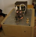
When used in RF amps, the 832 was mounted with the socket recessed below the chassis, so that the largest diameter of the bulb be at the same level that the chassis.
This was done for shielding reasons and does not apply for an audio design, except than ... that helps cooling the tubes by air coming from the bottom of the box around it.
Go further !
Yves.
Just a cosmetic hit.
When used in RF amps, the 832 was mounted with the socket recessed below the chassis, so that the largest diameter of the bulb be at the same level that the chassis.
This was done for shielding reasons and does not apply for an audio design, except than ... that helps cooling the tubes by air coming from the bottom of the box around it.
Go further !
Yves.
ok... what's the best way to get rid of oscillations on the 832?
all i can hear is shortwavestations in my loudspeaker.... 😎
(it's a hot receiver..)
all i can hear is shortwavestations in my loudspeaker.... 😎
(it's a hot receiver..)
Mount a pair of grid stopper resistors (say about 1K - 10K) right at the 832 grid pins, this should help.. Sometimes a small choke or resistor (~10 ohms) at the plate may also be employed.
Triatic, nice work! 🙂
What are those things that you used for connecting to the 832's plate pins?
What are those things that you used for connecting to the 832's plate pins?
Triatic, the schematic is the one posted in Post #30 yes?
It seems you already have grid stopper resistors. Make sure the resistors are soldered with their body as close to the base grid socket as possible. VHF valves kinda like to pick up all sorts of VHF junk. The 6C45 is one known for oscillation, see some precautions used in the "Kugelis" amplifier here. Grid stoppers and plate stoppers are used in addition to ferrite beads on the heater along with a ceramic bypass cap across the heater.
No idea!
kevinkr said:Mount a pair of grid stopper resistors (say about 1K - 10K) right at the 832 grid pins, this should help.. Sometimes a small choke or resistor (~10 ohms) at the plate may also be employed.
It seems you already have grid stopper resistors. Make sure the resistors are soldered with their body as close to the base grid socket as possible. VHF valves kinda like to pick up all sorts of VHF junk. The 6C45 is one known for oscillation, see some precautions used in the "Kugelis" amplifier here. Grid stoppers and plate stoppers are used in addition to ferrite beads on the heater along with a ceramic bypass cap across the heater.
Originally posted by Mr. Triatic
we can make a quiz out of this.. -what on earth are the wooden parts taken from?
No idea!
audiousername said:Triatic, nice work! 🙂
What are those things that you used for connecting to the 832's plate pins?
International shortwave broadcasting band tuning coils. 😀
Tip: If you'd like to explore DX on longer wave bands yank that 832 and drop in an 829.
The project looks great.
Trees?Mr. Triatic said:we can make a quiz out of this.. -what on earth are the wooden parts taken from?

Mr. Triatic said:ok... what's the best way to get rid of oscillations on the 832?
all i can hear is shortwavestations in my loudspeaker.... 😎
(it's a hot receiver..)
To hear radio, you need, at least, an antenna and a detector.
The power cord, the loudspeaker wires and the signal cables can act as antenna.
Look first at right grounding of the signal cable shield to the chassis frame.
Also ground one side of each of each loudspeaker wire.
The power cord seldomly poses problems, but if you have a ground wire at the wall socket, insure it is tied to the chassis frame too.
Any tube can act as a detector, specially if wrong biased, please post the current schemo with values.
Oh, and, does the amplifier alone play radio, I mean even with input cables unplugged ?
Yves.
*LOL* ok, Brett is correct, sort of...
-The plate connectors are made of an old powerconnector for motherboards, i chopped into pieces with three wiresections each and spared one cable (in the middle) and then put some heatshrinking tube over it.
-I will put in some gridstoppers and try different kind of earthing alongside with ferritebeads on the filamentsupply..
->rcavictim: you say that 829 are even more prone to oscillate than 832? i have a few NOS of those as well, i might try them 😎
if i cant get it to work, i replace the 832 with two EL34 instead.
Mr. Triatic said:[B
->rcavictim: you say that 829 are even more prone to oscillate than 832? i have a few NOS of those as well, i might try them 😎
[/B]
What I meant was since the 829 being larger has higher inter-element and stray capacitances than the 832. The higher capacitance would theoretically 'tune' your radio receiver to longer wavelengths. I was trying to be funny/clever.
I also thought of 'trees' answer but didn't bother posting it. In aftermath I should have since that joke got a much better audience response!

My solid state homebrew mag phono preamp was acting as a shortwave receiver once. Fidelity was excellent! 😀
rcavictim said:What I meant was since the 829 being larger has higher inter-element and stray capacitances than the 832. The higher capacitance would theoretically 'tune' your radio receiver to longer wavelengths. I was trying to be funny/clever.
lol... 😀 I get it now. A tad too subtle perhaps...
Mr. Triatic said:The plate connectors are made of an old powerconnector for motherboards, i chopped into pieces with three wiresections each and spared one cable (in the middle) and then put some heatshrinking tube over it.
Is the heat a problem? I have a few old motherboard power connectors around perhaps for an 829, but I have a horrible feeling they might melt
 The plate pins were originally meant to be mounted to some sort of heatsinking device (like some Eimac valves), weren't they?
EDIT:
Mr. Triatic said:(well, hopefully it sounds better than it looks...)
It looks great! No need to apologise.
Now to find a woman that'll say that, most of the time. Without the sarcasm.Mr. Triatic said:Brett is correct
From actual experience (I own a SE EL34 amp that I personally built) A SE El34 amp with a 5687, E182CC or 7044 tube as the driver operating at a idle current of around 12 - 15 mA is a very versatile, economic and sonically excellent piece of equipment. You have to use good output transformers ( I use Magnequest TFA204s with the EL34s idling at 50-55mA depending on the brand and build of tubes) and good components (Kiwame carbon films. Mill's wirewounds and Aeon caps) but the payoff is substantial when you listen to your favorite old songs and hear what the engineer heard when he recorded it. You also have the advantage of being able to subtlety change the sound by switching between driver tubes. The bass is solid but not overstated (in triode mode) but is present and accounted for. A lack of solid bass in my music is like trying to walk without a big toe on one foot. You can do it but you are definitely aware that it is missing. I have posted the schematic for the amp I built below. I hope you or someone will try out this simple yet excellent (the sound, not necessarily the design) circuit and enjoy the value and the financial practicality of it. BTW, A EL34 in triode mode can achieve a comfortable 6 watts at moderately high (90mA with the Electro harmonix and CEDs) which gives you a greater range of loudspeakers that it can be used with. If I can ever achieve the linearity and purity of a 2A3 using a EL34 I will immediately tell everyone all about it. In the mean time this amp, utilizing cheap, easily obtainable and affordable tubes (except for the E182CCs and the highly sought after and over hyped Mullard EL34s) does not leave you dissapointed and yearning for it's distant and far more expensive cousins. Merely mildly curious about what all of the DHT hoopla is about. Enjoy if you choose to.
G
G
Attachments
well, i still have problems with the oscillations, all i have managed so far is adjusting the oscillation frequency... 8-/
but i wont give up!! i plan to re-route the grounding as next step.
-i was thinking about the gridresistor going to B+ is that a correct value or should i change?
->Brett: good luck... i've been trying to find one for years now, no success yet... i think we've run out on those
->audiousername: mine connectors show no "melting-tendencies" , just not yet, but 'ill keep my eyes open (or the nose..)
-but now it's time to fill my belly with lot's of food and a huge amount of beer!!
- Status
- Not open for further replies.
- Home
- Amplifiers
- Tubes / Valves
- Single-end... which tube?