Hello All,
Scratching my head about the way audio output transformer manufactures provide transformer specifications that call out a maximum primary current. It seems to me that selecting a transformer based on maximum current is odd. Also seems to me that the idle current selected should fall at the center of the transformer’s hysteresis loop for least distortion.
I just received a pair of Transendar 10 watt, 90 ma maximum transformers.
Where do you suppose that 90 ma maximum fits on the hysteresis loop?
Thanks DT
Last edited:
The centre of the hysteresis loop is zero DC - not much use for SE! Max current for an SE OPT is probably where the primary inductance starts falling too low. Less likely is the point where copper heating gets too much.
Remember that when AC is present the secondary current almost matches changes in the primary current, so flux stays almost the same.
Remember that when AC is present the secondary current almost matches changes in the primary current, so flux stays almost the same.
It's called the "minor loop" where the AC flux circulates...on top of the DC offset..
You have the SUM of the DC and AC flux density.....
Lets suppose you want to limit the total flux to 10k Gauss..
The DC flux density can be at 5K Gauss and the AC minor loop will swing 5k Gauss..meaning up to 10K and down to 0 origin....
If you want to stay off the origin since it is non-linear in this region.. you can DC bias at 6k Gauss and then have the AC flux swing 4k Gauss up to 10k Gauss and down to 2k Gauss..
The more turns you add the greater the DC flux will increase, but the AC flux goes down, so you have a smaller minor loop...
Hello All,
Scratching my head about the way audio output transformer manufactures provide transformer specifications that call out a maximum primary current. It seems to me that selecting a transformer based on maximum current is odd. Also seems to me that the idle current selected should fall at the center of the transformer’s hysteresis loop for least distortion.
I just received a pair of Transendar 10 watt, 90 ma maximum transformers.
Where do you suppose that 90 ma maximum fits on the hysteresis loop?
Thanks DT
Unfortunately transformer cores do saturate, a bad thing. The maximum allowable magnetic field is Bmax = Bdc + Bac, Bac depends on AC voltage, Bdc depends on DC current, a serious transformer manufacturer make the calculations for an almost linear Bac hysteresis loop on condition to not exceed Bdc; this condition is equivalent to not exceed Idc.
Where do you suppose that 90 ma maximum fits on the hysteresis loop?
Thanks DT
Hi,
At one end of the loop and for SE use the standing current should be 45mA.
rgds, sreten.
Hi,
At one end of the loop and for SE use the standing current should be 45mA.
rgds, sreten.
From Maxwell's equations it follows that
AC magnetic field
Bac(max) = (Uac x 10⁸) / (√2 π fo S Np)
DC magnetic field
Bdc(max) = [4 π μ Np i(DC)] / (9 l)
Where
i(DC) = Primary DC current [A]
l = Magnetic circuit length [cm]
Np=Number of primary turns
S=Core area
μ=Magnetic permeability including the air gap
i(DC) is provided by the manufacturer, it is i(DC) not 2i(DC)
i(DC) is provided by the manufacturer, it is i(DC) not 2i(DC)
Hi,
Well I assumed wrong. Fair enough, A toss up between the two.
Saturation current of the core is easy to measure, so you
specify that, or half that for single ended use. Rethinking
it makes far more sense to specify SE standing current.
rgds, sreten.
So we have it. We have theory and formulas.
We have standing idle DC current.
On top of the DC idle current we have AC signal current. For the greatest symmetrical AC current swing what will the standing DC idle current be for this Transendar 10 watt 90ma maximum current transformer?
Or put another way 30ma standing DC current may be too low. 100ma may be too high? I am guessing that the stated 90ma maximum may be pushing up against the too high end for optimal symmetrical AC current swing.
I am looking for the DC current that allows for the greatest symmetrical AC current swing.
DT
Hi,
Then you need to know the saturation current and simply halve it.
Which I suspect is the given current rating. Your overcomplicating.
rgds, sreten.
Then you need to know the saturation current and simply halve it.
Which I suspect is the given current rating. Your overcomplicating.
rgds, sreten.
Hi,
Well I assumed wrong. Fair enough, A toss up between the two.
Saturation current of the core is easy to measure, so you
specify that, or half that for single ended use. Rethinking
it makes far more sense to specify SE standing current.
rgds, sreten.
1.- From the beginning we are talking about SE OPT, for PP OPT, the DC components cancel each other because the current flow through two windings with opposite helicity, then Bdc=0
2.- There is no defined "saturation current", transformer core saturates due to magnetic field B, Bdc(max) or Idc(max) is a designer's choice.
It follows that you do not need to halve nothing.
So we have it. We have theory and formulas.
We have standing idle DC current.
On top of the DC idle current we have AC signal current. For the greatest symmetrical AC current swing what will the standing DC idle current be for this Transendar 10 watt 90ma maximum current transformer?
Or put another way 30ma standing DC current may be too low. 100ma may be too high? I am guessing that the stated 90ma maximum may be pushing up against the too high end for optimal symmetrical AC current swing.
I am looking for the DC current that allows for the greatest symmetrical AC current swing.
DT
Agree, we have theory and formulas, only need to interpret them properly.
Transformer manufacturer say that if you put more than 90 mA DC, in the best case you will not obtain 10W, in the worst case you will saturate (more probable) and even magnetize permanently your transformer core (less probable).
As the effect of DC current is move the hysteresis loop on the plane BH, the best result is obtained close to nominal 90 mA, then idealy (well designed trafo) the hysteresis loop will be in the I cuadrant and you can avoid zero crossing.
Transcendars website shows ratings as maximum DC bias current:
Transcendar Transformers - 10 Watt SE
That seems self explanitory but the easy way to know for sure would be email or phone them.
Transcendar Transformers - 10 Watt SE
That seems self explanitory but the easy way to know for sure would be email or phone them.
It follows that you do not need to halve nothing.
Hi, Utter nonsense. Optimum current is halve something, rgds, sreten.
Which is most likely halve the deemed DC saturation current.
Hi, Utter nonsense. Optimum current is halve something, rgds, sreten.
Which is most likely halve the deemed DC saturation current.
You are still confusing maximum DC bias current with your "DC saturation current"
I know that my Tarzan-English is not easy, but you don't need a cryptologist, so here go again...🙄
In order to avoid core saturation you must take
B(max) = Bac(max) + Bdc(max) =
= {(Uac x 10⁸) / (√2 π fo S Np)} + {[4 π μ Np i(DC)] / (9 l)}
The most usual choice is Bac(max) = Bdc(max), with Bdc(max) you can calculate i(DC) i.e. maximum DC bias current.
It is not a saturation current, it is a design choice to avoid core saturation.
There is another magnetic field H associated with primary AC current, but it cancels with the corresponding magnetic field H associated with secondary AC current.
i(DC) i.e. maximum DC bias current is provided by the manufacturer, so no need to halve any current, if you want to halve something then halve the magnetic field B(max). Happy? 😛😀
Last edited:
Hi, Utter nonsense. Optimum current is halve something, rgds, sreten.
Which is most likely halve the deemed DC saturation current.
Utter nonsense is a generic definition of "maximum current". A maximum current can also be that current generating a high current density in the copper wires. Typically limited to 3A/mm^2 as a safe limit and also because a limiting factor at high frequency (skin effect and proximity effect which start to join in already in the audio range).
Actually it's easy to get close to 5A/mm in small transformers. For example if one uses 0.14 mm copper wire (0.16 mm including insulation) for the primary (in order to fit enough turns to get a good inductance for higher impedances in the 5-10K range) then current density is 5.85 A/mm^2 @90 mA DC.
Among serious manufacturers, it is customary to define a max recommended current which clearly is a max operating current that will allow the specified power. Max current is not synonym of saturation current. Have a look at serious specifications sheets.
However this is not the only bad thing. 10W alone doesn't mean anything! 10W @50/60 Hz is not like 10W @30Hz. Defining power without frequency is normal for supply transformers where the operating frequency is fixed at 50/60 Hz.....
If the transformer is 10W at 50/60 Hz then it will only be 3.6W and 2.5W at 30 Hz, respectively. Doesn't look great!
It doesn't quite work like that. The core does not see the AC signal current in the primary, as most of it is cancelled by AC signal current in the secondary.DualTriode said:On top of the DC idle current we have AC signal current.
It doesn't quite work like that. The core does not see the AC signal current in the primary, as most of it is cancelled by AC signal current in the secondary.
This is not totally true, actually transformer core can see the magnetic fields due to AC current, even when they mostly cancels each other.
Let's consider maximum values for the fields B and H
Bac(max) = (Uac x 10⁸) / (√2 π fo S Np)
Hac(max) = (4 √2 π Np iac) / (9 l)
Effective power must be
P = η Uac iac = (9/4) η fo S l Bac Hac x 10⁻⁸
Then, minimum needed core area will be
S = (4 P x 10⁸) / (9 η fo l Bac Hac)
Multiplying and dividing by μ on both members
S = (4 μ P x 10⁸) / (9 η fo l Bac²)
This is in agreement with the rule of thumb
S = 1500 √(P / fo Bmax)
That's why a 100 W transformer is bigger than a 10 W transformer.
most symmetrical AC current swing
Dr. Dave,
Let us look at this keeping it simple and adding complexity only as we need it.
We have the B+ voltage in series with the output transformer primary winding in series with the Single End Triode anode and finally the Rk connecting to earth.
At idle there is a DC current through the output transformer primary winding. As an AC signal is applied to the grid the current through the output transformer primary winding will vary in response to the applied signal.
The goal is to select an idle current that allows the most symmetrical AC current swing with the least transformer induced distortion at the output.
The question is; how does the specified 90ma maximum bias current address optimizing the performance of this Transendar SET transformer? Or is the 90ma max just a way to limit the temperature rise to some point where the thing will not self-destruct?
An added note this Transendar transformer is manufactured not too many miles from my home here in California. Transendar transformers enjoy a good reputation among the DIYaudio users including TubeLab.com builders. I bought a couple versions of Transendar transformers as well as Edcor transformers to play with on the bench.
DT
It doesn't quite work like that. The core does not see the AC signal current in the primary, as most of it is cancelled by AC signal current in the secondary.
Dr. Dave,
Let us look at this keeping it simple and adding complexity only as we need it.
We have the B+ voltage in series with the output transformer primary winding in series with the Single End Triode anode and finally the Rk connecting to earth.
At idle there is a DC current through the output transformer primary winding. As an AC signal is applied to the grid the current through the output transformer primary winding will vary in response to the applied signal.
The goal is to select an idle current that allows the most symmetrical AC current swing with the least transformer induced distortion at the output.
The question is; how does the specified 90ma maximum bias current address optimizing the performance of this Transendar SET transformer? Or is the 90ma max just a way to limit the temperature rise to some point where the thing will not self-destruct?
An added note this Transendar transformer is manufactured not too many miles from my home here in California. Transendar transformers enjoy a good reputation among the DIYaudio users including TubeLab.com builders. I bought a couple versions of Transendar transformers as well as Edcor transformers to play with on the bench.
DT
Last edited:
It probably doesn't address that issue, except in the sense that too high DC current will reduce primary inductance and hence reduce low frequency response.DualTriode said:The question is; how does the specified 90ma maximum bias current address optimizing the performance of this Transendar SET transformer?
Possible, but unlikely. SE OPT max DC current is usually based on avoiding core saturation.Or is the 90ma max just a way to limit the temperature rise to some point where the thing will not self-destruct?
I don't know what the problem is. My post 2 already explained it.
Or is the 90ma max just a way to limit the temperature rise to some point where the thing will not self-destruct?
Temperature is possibly the last problem you might have in OPT's. It's not a supply transformer.
I think you better ask the manufacturer for details as there is no unique way to with a transformer with those unspecified specifications!!
This also shows that in the end it is better to write down and publish a serious datasheet. Less waste of time because all people need to know is already written and actually they can always pick the right transformer without wandering what it can be used for....
Some years ago I built for my friend one A2 capable 300B SE with 5k/10W OPT (he bought this from Transcendar directly).
This transformer is well built one, but both (primary and secondary) DCR is on the high side (381R/0.85R), so copper losses are significant.
For enough headroom I lifted B+ to 440V.
The amp (gyrator loaded C3g, powerdrive, fix bias 300B) capable 10W, the sound is very attractive and powerfull (within its limits).
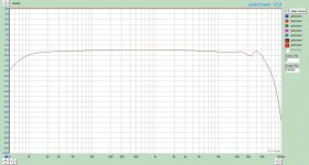
Measurement:
The manufacturer's frequency response promise is very optimistic -as usual-. 🙂
The measurement (1V, 700R generator impedance) not bad, but HF rolloff is stronger than in datasheet (first pic: -1dB: 7Hz..54kHz, about 0.5dB dip at about 34kHz).
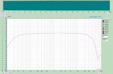
The power bandwidth is suitable:
at 10W/8R -second picture-
-1dB: 25Hz..32kHZ
-3dB: 13Hz...54kHz
This transformer is well built one, but both (primary and secondary) DCR is on the high side (381R/0.85R), so copper losses are significant.
For enough headroom I lifted B+ to 440V.
The amp (gyrator loaded C3g, powerdrive, fix bias 300B) capable 10W, the sound is very attractive and powerfull (within its limits).
Measurement:
The manufacturer's frequency response promise is very optimistic -as usual-. 🙂
The measurement (1V, 700R generator impedance) not bad, but HF rolloff is stronger than in datasheet (first pic: -1dB: 7Hz..54kHz, about 0.5dB dip at about 34kHz).
The power bandwidth is suitable:
at 10W/8R -second picture-
-1dB: 25Hz..32kHZ
-3dB: 13Hz...54kHz
Attachments
Last edited:
- Status
- Not open for further replies.
- Home
- Amplifiers
- Tubes / Valves
- Single End Transfomers, The hysteresis loop and maximum current