I'll have to go back and look. The original file should be an easy pick because of the technical difficulties of the test. The oddball "wires" in the loop were all high impedance. That high impedance led to significant signal attenuation and noise. On some of the looped recordings I tried to remove the noise with software filters, and the filtering was audible. I would not do that again.Am I mistaken?
The test is worth running again and making improvements. The input of the sound card needs to be of a higher impedance to lessen the signal loss. The fruits, veggies, mud and other goofy conductors might need to be shielded. I started down that path, but never finished it. When I get settled in my new place, I'll probably do an improved version.
@Jakob2 The key to the files is here.
https://www.diyaudio.com/community/...bout-a-potato-or-even-mud.236248/post-3509865
Did I score all the listeners? Don't remember.
But that's enough - I don't want to hi-jack this thread. Just pointing out a test that I had posted. Read it and make of it what you will.
https://www.diyaudio.com/community/...bout-a-potato-or-even-mud.236248/post-3509865
Did I score all the listeners? Don't remember.
But that's enough - I don't want to hi-jack this thread. Just pointing out a test that I had posted. Read it and make of it what you will.
I would suggest separating the DAC and ADC to closer simulate the most common use case for interconnects.The test is worth running again and making improvements.

That is a correct statement. Strand oxidation will impact skin depth as well as proximity effect caused by other conductors.Something else to wonder about: Might eddy currents force current flow laterally across wire strands including through copper oxide surface contamination?
Niobium titanium superconducting cables with copper jacketed wires will have their non DC performance compromised because of conductor to conductor eddy currents. This effect can get very bad as resistance of the copper jacket of the wires really drops as liquid helium temperatures are reached. If we want faster ramp speeds in a super magnet, we have to make sure the copper is of lesser quality (so to speak) such that the mean free path in the copper doesn't become long. Work hardening, impurities all help reduce the effect.
CFT is correct in that all grain boundaries do is increase resistance a tad. With a mean free path orders of magnitude shorter than the grain size, I wouldn't worry.
Your surface state mention and trapping electrons to be released later....do you have any citations on that topic?
John
Member
Joined 2006
It's due to some charge trapping effect from the surface states of plastic (against the copper surface)... I dont have any reference on hand... as I base it on other materials characterization experience I have in the past.. but a quick google search landed on this article:
https://www.researchgate.net/public...nd_Negative_Electron_Affinity_in_Polyethylene
See it mentions in the first paragraph..."mobility of carriers, charge trapping, and charge induced degradation...in polyethylene "...see ref. #1
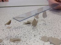
Btw, this is a tell tale photo: 😁
https://www.researchgate.net/public...nd_Negative_Electron_Affinity_in_Polyethylene
See it mentions in the first paragraph..."mobility of carriers, charge trapping, and charge induced degradation...in polyethylene "...see ref. #1
Btw, this is a tell tale photo: 😁
Attachments
Last edited:
Ah, thanks. Charge trapping in the insulation deals more with the capacitances of the insulation and the surrounding environment, as well as DA.. I work heavily with kapton, and man does that stuff do weird things. It's dielectric absorption and recovery is unbelievable.. I hipot a magnet to 5kV, discharge it to zero volts, disconnect the short, and the kapton recovers to roughly 20% of the test voltage. In my hi-pot class, I overemphasize keeping it shorted for at least as long as it was energized.
For our audio stuff, I find it to not be a real issue.
John
For our audio stuff, I find it to not be a real issue.
John
Can you measure that during the charge up? Does a Kapton insulated coil need more Joules to energize than some other insulation?and the kapton recovers to roughly 20% of the test voltage.
Question about charge carriers and noise: If charge carriers move according the electrical signal to then interact with grain boundaries, then is the sort-of excess noise due to the signal amount to signal-modulated noise (noise floor modulation as seen on an FFT)?
Until you will cite relevant information from authoritative sources, this qualifies as your usual pataphysics.
We don't bother measuring it. The test is just insulation integrity, how much charge is required to get to 5kV isn't what we worry about.
But I'm sure that it does need more joules to rotate them there mollycules. Other insulations, not sure about. We use kapton because it's very radiation resistant and it remains flexible at 4.5K. The real problem is, one magnet charged to 1kV probably isn't lethal, but a string of 144 of them certainly can be. Once you get over 400 volts, the "incident" will flash through the skin surface at both entry and exit point, and the much lower internal resistance of a human body really conducts the current hard, and possibly fatal.
The old insulation testers were just a knob with a voltage meter and a current meter, old school. Now they picked up some newfangled computer controlled fancy shmancy testers, and just set a slew rate.
jn
Yes, I know this from direct experience. So do many tube fans. 200 watt/seconds @ 450V leave a mark.Once you get over 400 volts, the "incident" will flash through the skin surface at both entry and exit point,
The idea about measuring the energy stored in the insulation was just idle curiosity. It might me interesting to know, either by calculation or by measurement.
The difference in resistance between different cables is negligible.
I have used 13 amp UK mains cable on my 225WRMS disco for 30 years.
I have used 13 amp UK mains cable on my 225WRMS disco for 30 years.
https://www.ecmweb.com/content/article/20885786/think-like-a-gfciI've never heard of a GFI that does that.
"...the UL standard requires that GFCIs trip with a 6mA ground fault even when the neutral and ground are connected. To meet this requirement, GFCIs trip when the load side neutral and equipment grounding conductors are joined, even if there is no ground fault."
Agree this could be unclear; I am off my main PC.
It seems to be an RF test, so yes probably inductance. I know, because I put an outlet next to the fusebox, and it false-tripped excessively. I moved the feed from the fusebox to a junction 8 feet away, say 14 feet total run, and it never false-tripped again.
When I am back at the main PC I'll look for better citation.
I thought they worked simply by sensing an imbalance between neutral and hot. Ground has no actual role. In France it's called a differential, and is on the main power panel. I've had GFI with no ground connected, and they stilll worked properly.the UL standard requires that GFCIs trip with a 6mA ground fault even when the neutral and ground are connected.
Or are you talking about something else?
That is what I understood.
A GFI works by running the neutral and hot through a toroid, six, seven turns give or take..as both are going through the toroid, they will cancel each other out assuming current is equal.
When current is off by 6mA, the transformer action produces a signal that says whoa, stop.
So old school GFI's just make sure what goes out on hot comes back by neutral. If they are not equal, trip.. trying to sense G/N connection is new to me.
A good thing, but I've not heard of it before.
The NEC allows the use of a GFI in an outlet that has no ground. Not sure what the relevant code reference is, but definitely found it. I really did not want to pull sheetrock to fix that one D##M outlet that is rarely used, just to meet some code guy..
jn
Leaves a mark where?? At the entry and exit wounds? Or, at the locations on the chest where they put the Defib pads?Yes, I know this from direct experience. So do many tube fans. 200 watt/seconds @ 450V leave a mark.
jn
edit: my apologies to the OP for the hijacking of the thread.... Just lost a co-worker, I've spent the last 15 years of my career trying to get upper management to work out a plan of succession in the event I get hit by a bus (or win powerball), the loss of a friend emphasizes the need to pass on information that is important... even if it is stream-of-consciousness..
Last edited:
Yes, I've seen that little toroid in the GFI. For main breakers, the difference is set to much more than 6mA. The trip current is dependent on the size of the main beak, as I recall. I remember our electro having to disable one a large main panel on one show. We were balanced between phases, I suppose.
LOL. On my hands. One bump, and othe hand a hole. A bank of caps in an old Graphlex photo flash did the nasty. Powered by two 225V batteries.chest where they put the Defib pads?
Here Earth Leakage Circuit Breakers are set to 30 mA, and big ones above 100A are sold in 300 mA, or with an external trip that can be varied as per installation.
Same principle, current imbalance caused tripping. Similar sensing transformer / coil.
Dust build up cleaning with gasoline is needed every few years.
The issue of metal conduit causing false tripping has to be considered.
Same principle, current imbalance caused tripping. Similar sensing transformer / coil.
Dust build up cleaning with gasoline is needed every few years.
The issue of metal conduit causing false tripping has to be considered.
If you can prove that audio use cable is affected by purity, please do so.
Normal max. use is less than 100 W/channel, a few light bulbs' worth.
Some of us are uncomfortable above 3 W/ch., which is comfortable in a normal room.
In terms of complexity of requirement, and tough working conditions, telecom cables and the main trunk cables from power stations have a far tougher requirement.
Given that transmission losses are significant, the power companies would have tried to use these to save power.
This has not happened.
Snake oil.
Get the appropriate poison, remove the bee in your bonnet.
That's the original function, since around 1972 (when they got smart enough to not need an Earth reference).When current is off by 6mA, the transformer action produces
Some years ago the problem of local E/N shorts diverting current was attacked by even smarter brains. The hallmark may be two doughnuts inside. The one I busted open a few years ago had that, and did not like being too close to the fusebox (to the main E/N jumper). Here is a TI paper.
https://www.ti.com/lit/ds/symlink/afe3010.pdf
"...In addition to a ground fault leakage detection, the AFE3010 can detect a grounded neutral condition which can also lead to a harmful shock from a connected appliance."
- Home
- Member Areas
- The Lounge
- Single-crystal OCC Wire - Can It Make a Difference?