I'm sure you'll love this one. The application note from Linear features a tuneable version.
http://www.linear.com/pc/downloadDocument.do?navId=H0,C1,C1154,C1009,C1026,P1213,D4101
http://www.linear.com/pc/downloadDocument.do?navId=H0,C1,C1154,C1009,C1026,P1213,D4101
Attachments
Thanks. I was looking for this schematic, a while back.
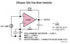
Not sure why it is "ultrapure", it's a conventional circuit.
Not sure why it is "ultrapure", it's a conventional circuit.
the multiple-lamps circuit in the link looks cool.
If only the frequency stability would be equally stiff as the distortion is low...
Rüdiger
If only the frequency stability would be equally stiff as the distortion is low...
Rüdiger
Frankly, NOTHING new about uing a Lamp for amplitude stabilisation in an Oscillator.
I came accross these about 20 years ago, and was THEN told that this ( lamps for amplitude stabilisation ) was as old as the hills.
I have also seen LAMP-LIFIERS which use bulbs as output emitter resistors ! ( some speakers used these too )
I'm not sure, but I think that the 1st HP product ( a low distortion audio oscillator ) used Excatly this ?
The long term amplitude stability is also not very good , and will even change with the ambient / enclosure temperature.
Also, the KEY to get that low distortion is matching the capacitors ( and resisitors ) to 0.1% !
Realistic in production or even for hobbysts ?
Amp_Nut said:Also, the KEY to get that low distortion is matching the capacitors ( and resisitors ) to 0.1% !
Why should they be matched 0,1% for low distortion?
This is the classical Wien bridge oscillator (try a Google search) that needs a gain of 3. The gain is set by the resistance and the positive temperature coefficient of the lamp in combination with the feedback resistor.
For low distortion the time constant of the lamp needs to be sufficient long otherwise it gives rise to second harmonics.
Cheers 😉
that first oscillator was the HP 200A invented in 1939. the real innovation that made it inexpensive and maintained low distortion and amplitude stability was the light bulb in the feedback loop. all other audio oscillators cost 6 times as much as HP's at the time, and the 200A blew all the others away with performance. simple, inexpensive and better.......and built in a garage workshop.......
- Status
- Not open for further replies.
- Home
- General Interest
- Everything Else
- Sine Wave Generator with bulbs (Sine-lightenment)