Don't bother with my Dad, nor his Father (he died in 1920).Hello, back in 1969 my dad and his father assembled a Sinclair Project 60 with the preamp, the power supply, the two power amp modules and the AFU (active filter unit).
I assembled the Project 60 !
Hi Steph_tsf
Many people got into Sinclair gear. Computers with wobbly memory plug-ins; special drive which was nothing more than tape spaghetti when floppy disks would have done; black watches that you had to press a button to light LEDS ... all trying to be 21st century before their time, and all wanting a bit better engineering. Fun days.
But regarding the amps, crossover distortion would have been awful I think for the reasons you mention. No biasing to speak of. Even RCA amps weren't that bad, and they weren't always the best ...
John
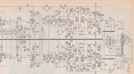
I have attached the schematic of the Voxson H202 amplifier in order to give you an idea of what a good quality amplifier was in Europe, back in 1969.
Reading it, I have the impression that Sinclair wanted to beat the Voxson H202, and in order to do so he used a constant current collector load in the VAS, instead of the capacitive bootstrap arrangement that you find in the Voxson H202.
Do you know other audio amplifiers back in 1969, using a constant current collector load in the VAS (apart from opamps) ?
But why did Sinclair dropped the symetric power supply ?
With a symetric power supply you need 1 bridge rectifier, 2 capacitors in the power supply and 0 capacitor at the outputs of the amplifier.
With an asymetric power supply you need 1 bridge rectifier, 1 capacitor in the power supply and 2 capacitors at the outputs of the amplifier.
So, clearly, the asymetric power supply is more costly than the symetric power supply !
This is an apparent paradox, as Sinclair was always in search of cost economies.
Now look, Clive Sinclair may have been scared by DIY people destroying their expensive loudspeakers, accidently throwing DC into them. Like it happen after you burn one of the output transistors. Like it happen after you do a wrong wiring. You see the picture ?
My opinion is that Clive Sinclair wanted to avoid a fame like "build a Sinclair amplifier and destroy your speakers".
Look now the Voxson H202 schematic. There is a fuse in series with each amplifier output. This is how Voxson was protecting your speakers. Sinclair could use such arrangement. Maybe Clive Sinclair found that the fuse was ruining the distorsion figure at low frequencies, a domain where his constant current collector VAS load was providing an extra low distorsion compared to the Voxson capacitive bootstrap arrangement.
Your opinion ?
Attachments
sinclair stereo sixty
hi there ,
may i got the circuit of the sinclair stereo sixty,please????
i got problem with transistor types.
Anyone else want this info by email?
hi there ,
may i got the circuit of the sinclair stereo sixty,please????
i got problem with transistor types.
I don't think that the amplifiers destroying themselves was because of the biassing circuit. My copy of the circuit shows MP8111 and BD155 for the output devices.
To keep within the transistor's Ic current rating (1.2 amp and 1 amps) the output power is limited to about 4 watts (into 8ohms)!
I remember tales at the time of the top of the transistor separating from the base part. That must have been the MP8111, I think that it was a black blob between two holes for bolts to hold it down.
I have an example of the Z30/Z50 amplifier here, and it is actually fitted with BD187 devices, which have an Ic of 4amps. The theoretical maximum power with these transistors is a whopping 64 watts (with a LARGE heatsink).
Ipeak 4A, IRMS = 4/1.414 = 2.83amps. 8 ohms, therefore V = 8 * 2.83 = 22.63VRMS (32Vpeak). Power = 22.63 x 2.83 = 64W RMS.
My calculations were fine, assuming that you had 64 volts for the power supply.
They ran on 35 volts, limiting the maximum output power to a 35volt peak to peak waveform. That's 17.5 volts peak, and 17.5/1.414 = 12.4 volts RMS.
Power is V x I, or V squared over R, substituting I = V/R from V = IR.
Therefore power = 12.4 squared over 8 = 19watts. Apologies for the error.
The amplifier should supply 32 watts into a 4 ohm load using a 32 volt power supply
with the same 4amp limit on the output transistors.
Sorry for this late reply. Voxson amp is very basic, should have had inclusive miller feedback and transistor bias stabiliser. Sinclair didn't like to add cost. Just the opposite, so omit bias diode whether necessary or not. Smaller heatsinks. No fuses. Cheaper cheaper.
But he rode a technological wave at the time. Should have gone upmarket instead of cost cutting all the time.
JOhn
But he rode a technological wave at the time. Should have gone upmarket instead of cost cutting all the time.
JOhn
HI.
Does anyone have any info / circuits for the Sinclair range of amps c1972.?
I think they were called the Z30 and Z50
Thanks
Andy
I understand it is quite late to return to this topic, but please let me share some info. First time I have built the Z30 was in late 1970's. I used my own PCB and the original quasi-complementary topology. I have lived with that amplifier for more than 20 years. When I first built it, I had only a scope and no distortion measuring instruments. Many had remained undisclosed to me, that times.
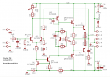
This summer, 45 years after the original project was created, I have decided to give it a chance and make some optimization and small changes:
1) input stage must be carefully balanced to get lowest distortion. This was not fulfilled in the original design.
2) There was no circuit for thermal stabilization of the bias current (and the amplifier was operated at very low bias current to prevent thermal runaway), so I have added a Vbe multiplier.
3) I have changed the output stage to complementary. MJL21194/3 output devices with MJE15030/31 drivers.
Z30 rev2014 is attached.
Attachments
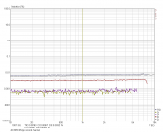
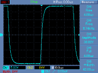
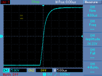
I have built the rev2014, placed into 3U/400mm 19" box and made a full set of measurements. When the amplifier is properly set up, that means well balanced input differential stage and optimally biased output stage, it performs surprisingly well. Attached please see a distortion plot vs. frequency for the amplifier that is supplied from 2 x 25V PSU, maximum output voltage is about 41Vpp and the measurement is performed at 38Vpp, i.e. about -0.65 dB below clipping. 38Vpp into 6.8 ohm load makes 26.5W. One can see that distortion is almost independent on frequency and is everywhere below 0.01%.
I have also prepared a description of this amplifier revision with BOM and measurements, though only in Czech language.
http://web.telecom.cz/macura/Sinclair_Z30_rev2014.pdf
I have also prepared a description of this amplifier revision with BOM and measurements, though only in Czech language.
http://web.telecom.cz/macura/Sinclair_Z30_rev2014.pdf
Attachments
Hi Pavel
Your modifications bring the Sinclair design up to something which is "1970 standard plus". I ran some simulations and don't see the effect of an imbalance in the input stage (you did not say how much offset there was, but if the two currents are within 10% I see a slight difference but between 0.015% and 0.014%. If the currents are seriously out of balance then I'd agree it is a poor design. I recall one design with 750uA and 250uA in the input stages as designed ... pretty hopeless, but this was not Sinclairs, I think. I used a BD140 driver and if this is replaced by a BC556B the distortion simulated falls to 0.004%.
Using the MJ(L)21193/4 output devices brings the 1970 standard to "plus" because these have excellent gain linearity, which should keep the distortion constant at higher power levels.
As such it probably won't sound "bad" but there is still the issue of transient distortion etc. although slugged by a 2k-1nF input this would limit the response, and may save it from overloading.
The next step to current "standard" as suggested by Self is to add degen emitter resistors and add current mirrors in the input stage and add a Darlington VAS with some local feedback.
Then as proposed by me is to use global feedback compensation and local "sprog stopper" capacitors as proposed by Cherry and input phase lag to get low crossover distortion at 20khz!
John
Nice update for an old classic 🙂This summer, 45 years after the original project was created, I have decided to give it a chance and make some optimization and small changes:
Hi Pavel
Your modifications bring the Sinclair design up to something which is "1970 standard plus".
Hi John,
thank you, this was the goal 🙂. With added mirror, emitter degeneration etc. it would make the Blameless, which was not my intent.
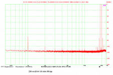
As you have correctly stated, input 2k + 1nF prevents the amp from slewing. Anyway, 19+20kHz result is above my expectations.
About sim, it performed worse in sim than in reality - which is interesting. Probably models question - I have used BC550's with beta = 700 etc.
Attachments
I still have a Z30 PCB without the blown output devices, resulting from a faulty headphone/speaker switch.
I bought it late '71, or early '72, from Comet in their new store @ Newhaven, Edinburgh.
Yes, Comet stocked all the project60 modules.
I'm going to play with it !
I bought it late '71, or early '72, from Comet in their new store @ Newhaven, Edinburgh.
Yes, Comet stocked all the project60 modules.
I'm going to play with it !
Last edited:
I know this is a very old topic but ...
I was looking for a schematic of a simple desk top amplifier
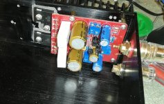
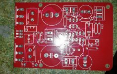
I made my simple modification based on the changes proposed by PMA I just replaced the output stage with one pair of Darlingrton transistors (BDV64 BDV65 OnSemi) I designed a small PCB (50 * 80mm) My amplifier is fed with quite low voltage 2 * 16V, gives a few watts
but I also tested with 2 * 27V power supply
The amplifier is easy to assemble and adjust, and it is stable
Sounds surprisingly good, especially the bass. No effort in driving my old speakers with 15 inch bass (Old French 3A Arioso Monitor model enceintes 3A - ARIOSO MONITOR)
Unfortunately, I lost Eagle files.
In Attachment
PBC, Amplifier during assembly,
diagram and simulation files
I was looking for a schematic of a simple desk top amplifier
I made my simple modification based on the changes proposed by PMA I just replaced the output stage with one pair of Darlingrton transistors (BDV64 BDV65 OnSemi) I designed a small PCB (50 * 80mm) My amplifier is fed with quite low voltage 2 * 16V, gives a few watts
but I also tested with 2 * 27V power supply
The amplifier is easy to assemble and adjust, and it is stable
Sounds surprisingly good, especially the bass. No effort in driving my old speakers with 15 inch bass (Old French 3A Arioso Monitor model enceintes 3A - ARIOSO MONITOR)
Unfortunately, I lost Eagle files.
In Attachment
PBC, Amplifier during assembly,
diagram and simulation files
Attachments
.
I have just bought a pair of Z30/50 amplifiers of EBAY (plus a Z20).
I think I have one of each.
So some hours of fun ahead!!
.
I have just bought a pair of Z30/50 amplifiers of EBAY (plus a Z20).
I think I have one of each.
So some hours of fun ahead!!
.
Hopefully working. Early models with MExxx transistors were run at or over their limits.
Not convinced that the TO-126 packaged OP transistors were any more reliable. You would certainly do better to upgrade these as Pavel did, with a bias current stabiliser, better OP transistors (a complementary pair MJE3055T/MJE2955T in TO-220 would be suitable) ... unless you want the "70's sound"!)
Not convinced that the TO-126 packaged OP transistors were any more reliable. You would certainly do better to upgrade these as Pavel did, with a bias current stabiliser, better OP transistors (a complementary pair MJE3055T/MJE2955T in TO-220 would be suitable) ... unless you want the "70's sound"!)
They have the TO-126 packages.
My plan was to upgrade both to a later more reliable spec similar to the one I made at Uni all those years ago. ( but keeping the look )
The other amp is the Z12 not Z20.
Andy
My plan was to upgrade both to a later more reliable spec similar to the one I made at Uni all those years ago. ( but keeping the look )
The other amp is the Z12 not Z20.
Andy
I rebuilt mine several times, added a EF buffer and "tape monitor" switch to the pre-amp. I also moved the tone controls, I think I moved the bass down...
The outputs were hopelessly optimistic and being a quasi output it needs a Zobel and inductor + resistor. The bias depends on the VAS CCS being thermal tracking so I would change it to diodes (1n4148) + smaller resistor. Mine had no emitter resistors or current limit... In the end I just replace the power amp modules with a DIY which never failed. If you actually want to use it, I would reduce the supply voltage or expect it to die regularly. In those days I had nothing and parts were hard to get. I learned a lot from "Sinclair" but today they are just ornaments, sentimental muses.
Planet Sinclair: Hi-Fi: Project 60
Schematics etc.
Last edited:
- Home
- Amplifiers
- Solid State
- SINCLAIR Amps from c1972