Really? Sure, with enough sensors and a processor, one could do some very fancy things. Even though I am convinced most comp systems are not as good as they could be, I am not sure they need to be THAT good as to need a computer. They question remains as how tight do we need to stay?
Hint: The higher the complexity, the higher probability for failure. With an analog system, we can predict HOW it will fail. With a digital system, we can't. ( Fly by wire planes scare me for this reason). We always want the bias system to fail lean. Can you do that with a processor? No.
Lower limit on not going too lean as this is very bad for distortion. Upper limit of not going into runaway as that is not good for one's bank account. Within those limits, how tight do we need to be for sound? -0, +100%? My simulations suggest that may be reasonable. Do I care if the 20K THD-9 @ full power into 4 Ohms jumps to .005 from .001 when 10W is still .0001 because the bias is a little fat?
In my case, I am still worrying about 4Vce or if I do MOSFET drivers, 2Vce. With BJT drivers, I have two different slopes. That would suggest I look at the Pass idea to compensate the driver stage as I can measure the delta on a class A stage, and then use a diode on the outputs. Getting our temperature measuring to track the non-linear change in the tempco is the problem.
Discovery: While playing with varius temps and square waves for inputs looking for hints of instability, I stumbled on what seems to be a fix I have not seen before.
I use two independent ccs, IPS and VAS. I found at clipping, the separation cleans a lot of things up. These are simple feedback pairs with the bias two 10K whose center point goes to a 10u cap. I added a .1u to the emitter of the reference transistor. It did wonders for glitchyness in the VAS with a square wave input and reduced the THD by 1/3.
Anyone seen this before? Any ill effects I have not considered yet?
Trying to get a conventional spreader to comp an EF3 accurately in my view is not possible. Too many variables thermally, electrically and then you have the dynamic of the program material on top of that.
What is "accurately" ?
The single vbe EF3 (below) , will go from 20ma to 35ma (0C to 25C) and
30-35ma depending on in- home use/abuse.
Before the trimmers were cleaned and readjusted... one channel was 10ma ,
the other was 35ma (spec for the sanken BJT's). That is the 30 YO EF3.
The newer "fancy pants" dual vbe on my H/K will stay within
5mA under the above conditions with 1-2ma stability in-house.
Now .. On-die thermal transients are a whole different story. The T-trak devices
(like in the HK990) would be the only answer to this "flaw".
Different OP devices always have their own "sweet spots". The sanken's
will sound good all the way down to 20ma .. while ON/Fairchild are best
at 60-80ma (across Re).
Perhaps the Sanken's were developed to allow for more "slop" in the Vbe
allowing for a cheaper, simpler circuit ?
OS
Attachments
Accurately in my book means at ant heatsink temperature, or, from cold, after a burst of high output level, if you measured the bias current it would be at, or very close to the ideal set value. This gives the lowest distortion of the OPS as well.
Most of the thermal comp circuits are straight line best fit comp types.
Most of the thermal comp circuits are straight line best fit comp types.
Discovery: While playing with varius temps and square waves for inputs looking for hints of instability, I stumbled on what seems to be a fix I have not seen before.
I use two independent ccs, IPS and VAS. I found at clipping, the separation cleans a lot of things up. These are simple feedback pairs with the bias two 10K whose center point goes to a 10u cap. I added a .1u to the emitter of the reference transistor. It did wonders for glitchyness in the VAS with a square wave input and reduced the THD by 1/3.
Anyone seen this before? Any ill effects I have not considered yet?
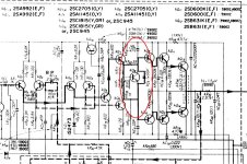
Yes , for the "blameless" independant (2Q)CCS's for IPS/VAS almost fully negate
tempco in these stages.
For red LED or double diode CCS's , it is best to tie both CCS's to the
same reference.
On the more "exotic side", a cascoded VAS with LED/zener is offset by
a simple red led CCS. If a 2Q CCS is used with a hawksford , using a 3
diode strings for the cascode will negate the CCS's tempco.
Below , the "badger like" circuit is nearly "null" (tempco wise) and the 2 CCS's
have fully independant decoupling. This really "cleans up" SW and clipping behavior. 😎
OS
Attachments
OS,
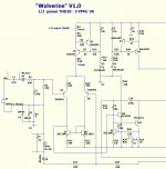
Based on your partial schematic:
Can you explain R6 and R7? I see them sometimes, but I have not seen a change in the model results.
I have not seen the use like D3 and D4. I will investigate.
Why should I worry about the IPS and VAS tempco? Should it not stabilize pretty quick and not too far above ambient?
Much thanks. Every little explanation helps in my overall understanding.
R6 & 7 are base stoppers. Help with stability.
D3 & 4 are power on (current flowing) indicators.
D3 & 4 are power on (current flowing) indicators.
OS,
Based on your partial schematic:
Can you explain R6 and R7? I see them sometimes, but I have not seen a change in the model results.
I have not seen the use like D3 and D4. I will investigate.
Why should I worry about the IPS and VAS tempco? Should it not stabilize pretty quick and not too far above ambient?
Much thanks. Every little explanation helps in my overall understanding.
Yes , some things the simulator will not show (CCS HF stability/base stopper).
The IPS/VAS tempco will increase/decrease VAS (I). In this case ,you could have a
very good OPS compensation only to have a wide error due to the
small signal stage tempco.
Most OEM's will aim for spare room cool (10C) to summer "party heat "(35-40C)
in their designs. Who wants to re-adjust OPS bias in the summer ?
The OPS is a different matter , it is dynamic in temperature - the reason for
the Vbe.
OS
I was thinking 35 junction temp was a reasonable target for the IPS. 50 for the VAS. Until I build it and measure, it is a bit unknown.
I guess one should plan on adjusting on the bench then swapping in a resistor for both IPS and VAS. I was actually planning on that for the servo as there is no such thing as a good pot. I was surprised how much change from 27 to 35 gave.
One piece I don't know yet is how dynamic the driver stage is. Even being class A, it will still be dynamic, just not to the extent as the outputs unless one were to force the issue. I think that is what Pass was trying to fix in the GFA's with the sensing of the driver emitter resistors. It was dropped, so I guess it did not work as well as planned. I understand the optical output feedback was dropped too.
Can't wait for my Linear Audio editions to get here. Two weeks and not yet. Getting worried.
Played for several hours with the ccs, and you are right again. Nothing shows up no matter how hard I try. If I stick with the feedback pairs I will be sure the board has provisions. Same on the drivers and outputs. It is still a toss-up for me between the feedback pair and a JFET ccs. Each has advantages in each location.
The more time spent in SPICE with clipping, square waves, and wider than expected sine waves, the more "funny" things show up. A guess on my part, but anywhere it can simulate a glitch or a ring, it is bad no matter how clean the output looks. Some are unavoidable. Some can be helped. Reality has to be even harder.
Not making headway with the TIAN probe, so I tried a few other things, like a 12MHz input and then measure across the IPS. Making tiny changes in comp values shows up much easier. Now I can see why when I tried to add a cap across the feedback resistor it went bad. I started at 3p, but it wants 1p. Now I have 75 degrees margin at 12M, where gain is zero. I don't know if it is just this design, but it seems the big knee is right around the zero gain, so it gets difficult fast.
- Status
- Not open for further replies.
- Home
- Amplifiers
- Solid State
- Simulation of thermal compensation