Dear All:
I'm trying to simulate an electret microphone.
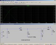
I'm using a 8v DC voltage source connected to an electret mic through a 4.4K resistor.
Is my simulation Ok with the 4.4K resistor in Parallel with the electret, or do I have to put the resistor in series?
Regards.
Alfredo Mendiola Loyola
Lima, Peru
I'm trying to simulate an electret microphone.
I'm using a 8v DC voltage source connected to an electret mic through a 4.4K resistor.
Is my simulation Ok with the 4.4K resistor in Parallel with the electret, or do I have to put the resistor in series?
Regards.
Alfredo Mendiola Loyola
Lima, Peru
Attachments
The voltage source by default has zero ohms output impedance and so the 4.4k does nothing. You could make it 0.44 ohms and it would still behave the same.
You need to make the voltage source behave like the FET capsule. What would be a typical output impedance ? 2 or 3k at a guess. You can add that directly to the voltage source by entering a value for the series resistance (right click the voltage source).
Where is your 8 volts derived from ?
You need to make the voltage source behave like the FET capsule. What would be a typical output impedance ? 2 or 3k at a guess. You can add that directly to the voltage source by entering a value for the series resistance (right click the voltage source).
Where is your 8 volts derived from ?
The DC source voltage comes from an Icom Radio. DC 8v.
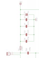
If I put the 4.4K resistor in series with the AC source it makes a voltage divider with my pot.
Is it Ok the simulation of the attached simulation?
Regards.
Alfredo Mendiola Loyola
Lima, Peru
If I put the 4.4K resistor in series with the AC source it makes a voltage divider with my pot.
Is it Ok the simulation of the attached simulation?
Regards.
Alfredo Mendiola Loyola
Lima, Peru
Attachments
Not quite 🙂
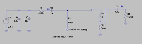
You need the 4k in series with the supply. The AC (audio) from the capsule has to be AC coupled to the next stage. C2 and C3 are just shorting the audio out.
Give me a minute, I'll try something.
You need the 4k in series with the supply. The AC (audio) from the capsule has to be AC coupled to the next stage. C2 and C3 are just shorting the audio out.
Give me a minute, I'll try something.
Try this. Look how I've set up the mic capsule voltage source.
I have read that the 4.4K resistor set the electret output impedance.
Does this output impedance have to be included in the model?
I don't know if ltspice is bearing in mind that 4.4K ohms of output impedance on the AC voltage.
Thank you for your help.
Regards.
Alfredo Mendiola Loyola
Lima, Peru
Last edited:
Yes it does. In my diagram that would be R3 which I put at 5k. FET mic capules need that resistor choosing in combination with the supply you want use.
I cheated a little and made the AC voltage source have a 10k impedance. If you right click the source you will see.
Let me try and come up with a better model for the mic... another idea. May or may not work.
I cheated a little and made the AC voltage source have a 10k impedance. If you right click the source you will see.
Let me try and come up with a better model for the mic... another idea. May or may not work.
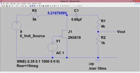
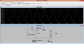
I've made the mic capsule a real FET, just like a proper capsule. It seems to work as expected. If you remove the pot loading then the output jumps up by the expected amount. So 5 k output impedance as shown,
I will use your last model to make my tests.
Thank you very much for your help.
Regards.
Alfredo Mendiola Loyola
Lima, Peru
You're welcome 🙂
(the 5k not only sets the output impedance, it will also alter the gain. Higher value equals higher gain. You need to look at your mic capsule data sheet and see what the recommended voltage range is. Many just about work down to 1.5 volts but are better fed from higher supplies such as your 8 volts. So choose you resistor to suit and then decide on the gain of the next stages. In practice it won't be very critical)
(the 5k not only sets the output impedance, it will also alter the gain. Higher value equals higher gain. You need to look at your mic capsule data sheet and see what the recommended voltage range is. Many just about work down to 1.5 volts but are better fed from higher supplies such as your 8 volts. So choose you resistor to suit and then decide on the gain of the next stages. In practice it won't be very critical)
I've made the mic capsule a real FET, just like a proper capsule. It seems to work as expected. If you remove the pot loading then the output jumps up by the expected amount. So 5 k output impedance as shown,
Can I remove the AC Series Resistence of 10 Meg Ohms from the AC source?
Regards.
Alfredo
You can. It shouldn't change anything much because the FET gate impedance is so high.
I have change the voltage DC Offset from -2.5V to 8V to mantain the graph line on 0dB.
Is it Ok?
Regards.
Alfredo Mendiola Loyola
Lima, Peru
Attachments
Its not really OK 🙂 Look at the gate current of the FET. It will be burning a hole in your screen at about 7.5 amps.
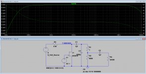
The reason for the high frequency roll off of my circuit is simply the 10meg series resistance I had in the voltage source. The real mic hasn't got that problem.
The practicalities of this are that it will work with a proper mic capsule. All you have to do is pick the correct the value of series resistor to suit the capsule.... and there is a lot of tolerance on that.
Note that the Yahoo LTspice group has several electret mikes models available, here is an example:
https://groups.yahoo.com/neo/groups/LTspice/files/ Lib/ELECTRET MICROPHONE/
I have no idea of their actual validity, but since the contents is directly vetted by Helmuth Sennenwald and indirectly by Mike Engelhardt, they shouldn't be too bad.
https://groups.yahoo.com/neo/groups/LTspice/files/ Lib/ELECTRET MICROPHONE/
I have no idea of their actual validity, but since the contents is directly vetted by Helmuth Sennenwald and indirectly by Mike Engelhardt, they shouldn't be too bad.
Hi,
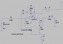
instead of a voltage source feeding a JFET that differs from typical Mic-JFETs, why not simply use a current source?
jauu
Calvin
instead of a voltage source feeding a JFET that differs from typical Mic-JFETs, why not simply use a current source?
jauu
Calvin
Hi,
instead of a voltage source feeding a JFET that differs from typical Mic-JFETs, why not simply use a current source?
jauu
Calvin
I'm simulating the electret microphone using a voltage source AC with an output impedance of 4.4K (Resistor between 8v and the electret capsule).
Rseries = 4.4K = electret output impedance.
I hope that this design works.
Regards.
Alfredo Mendiola Loyola
Lima, Peru
Attachments
Merci les gars pour vos schémas, vous m'avez sauvé mon projet d'élec, gros big up à vous les sangs !
Merci les gars pour vos schémas, vous m'avez sauvé mon projet d'élec, gros big up à vous les sangs !

English only please. Rules.
Thank you guys for your schemes, you saved me my elect project, big big up to you bloods!
- Home
- Source & Line
- Analogue Source
- Simulate an electret microphone LTSpice