Smart to learn from others' mistakes and a fool at his!
This rule does not apply when it comes to forums because each hears differently and the only sure way to find perfection is that try myself.
PRP, styroflex, Muse KZ, 2sk369 work fine on my others audio components. Superior is in my speakers and satisfied with them, because i bought Silver.
Despite disappointment I have not lost interest, so I look for the reason for such poor sound and notify you of changes to each component. Expensive components, it's just money, isn`t it. As a collection of watches, jewels or other hobby
Some caps sound pleasing in electronics and not so pleasing in speakers. It works the other way around as well, of course. I would confirm operational conditions as Salas stated, then change syroflex, then Silver Z.
impuls:
I've changed a lot of caps...including some to Jantzen silvers. I don't think the caps or resistors are the problem...unless they are the wrong value. I think the Jantzen silvers sound great. Very open.
I'd double check your resistor/cap values but I bet the problem is with the the conversion to folded and or a wrong value part.
Both channels doing the same thing?
No oscillation, R4 4,3V, Led diodes 8,3V, source resistor 130 ohm R13 3k33 for folded. Fol old version collector of Q3 is on 11V. Source resistors are 8.2 ohm R13 1k2.
First i try disconnect one 2sk369 and change R13 for lower. Then i will change Q3 connection like on old riaa. You'll be notified of the results. Don`t worry, i have to make it to work right
You were supposed to use 2SK170BL or I remember wrong? Want me to review it for 3X369BL? Tell me the idss you used please.
Allen Wright's audio guru opined that the styroflex caps were evil!
I have never used them since I heard this at a particularly impressionable stage in my DIY career and did not need to know. One less thing to have to change.
I was surprised when I got them in my kit.
I am using variable air caps in the trimming position.
Hope to have my phono stage working this weekend. (How many times have I made that claim? Too many ...)
First i will change silver at interstage to a styroflex and try to increase current at first stage. On old riaa i had 20mA through first stage, how i have only 4.7mA (1.56mA each 2sk369)
Salas, first riaa had 2x2sk170 with 8.2 ohm at source and have 9mA each. Now i have 2x2sk369 with 130ohm at source and 1.56mA each
The quickest way to test is that change resistors values of resistors at lowest and listen. I do it now
Salas, first riaa had 2x2sk170 with 8.2 ohm at source and have 9mA each. Now i have 2x2sk369 with 130ohm at source and 1.56mA each
The quickest way to test is that change resistors values of resistors at lowest and listen. I do it now
Last edited:
I would count its a gain and cart match thing or some bias error. Much capacitance from 3X369 is not a good thing for a medium output MM cart treble loading also but it does not explain missing the bass.
First i will change silver at interstage to a styroflex and try to increase current at first stage. On old riaa i had 20mA through first stage, how i have only 4.7mA (1.56mA each 2sk369)
Salas, first riaa had 2x2sk170 with 8.2 ohm at source and have 9mA each. Now i have 2x2sk369 with 130ohm at source and 1.56mA each
Don't change the input stage configuration in a hurry to telescopic cascode. There are many here who enjoy the folded for MM. You got a 2.5mV Technics MM right?
Why you don't simply copy the 43dB config with single 369BL from the FSP guide that many enjoy, and start from there? Then you will know where you stand and after some voltage readings we could add the odd 3dB more you may like etc.
P.S. What you describe as previous version with 9mA on each input K170 sounds like an MC stage to me. Have you confirmed the gain? Maybe you got an MC cart in the end, that is why its sounding like an old radio on MM gain?
first try: with higher Id at first stage i lose some details in midrange but now i have body of the singer. crackling on vinyl has a depth.
What you will end up with, put it in a circuit diagram with idss and check voltages noted for us to review. Else we are at a loss of what happens in your version so to be of real help. Confirm 1kHz gain also if you may.
I've purchased this Chinese case for my PSU. One of the covers has slots the other doesn't. Thermally I should use the slotted one as the top but since the external psu is to minimize interference and most probably will be placed on a shelf below FSP I decided to put the NON slotted panel on top. What do you think ?
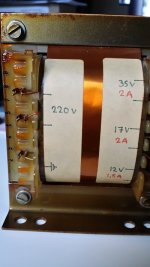
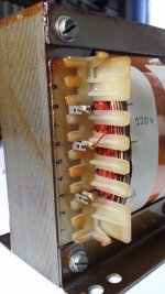
Another think that I want your advice is where to connect xformers screen. As you can see my xformers have a copper band around their core. Where should I connect the corresponding terminal ? At the xformer's mounting screw? Bring the the two wires at the back where mains earth will be connected to the chassis ?
Another think that I want your advice is where to connect xformers screen. As you can see my xformers have a copper band around their core. Where should I connect the corresponding terminal ? At the xformer's mounting screw? Bring the the two wires at the back where mains earth will be connected to the chassis ?
Attachments

Non slotted on top sounds fine. Those chunky trafos won't get hot anyway.
Those look like Gauss bands to me. Do nothing for those, they are just to oppose leakage flux. Link the IEC earth prong with a short cable to a chassis lug near it.
Those look like Gauss bands to me. Do nothing for those, they are just to oppose leakage flux. Link the IEC earth prong with a short cable to a chassis lug near it.
Gauss band ? My first search brought up this https://www.youtube.com/watch?v=bJzzXa-338Q 🙂
A more serious attempt brought up this excellent post http://www.diyaudio.com/forums/power-supplies/220511-transformer-shielding.html but it will take me ages to digest it...
It seems that there are both gauss/belly bands and electrostatic shields..
I presume that in this case the transformer's earth connection tab should connect (with a long wire) to the chassis lug you mentioned.
Attachments
Despite disappointment I have not lost interest, so I look for the reason for such poor sound and notify you of changes to each component. Expensive components, it's just money, isn`t it. As a collection of watches, jewels or other hobby
Can you post here the real values of the résistors and caps on the riaa filter and first stage load ?
I would like to input those in my riaa calculator to verify if the results comply with your subjective sound results.
Gauss band ? My first search brought up this https://www.youtube.com/watch?v=bJzzXa-338Q 🙂
A more serious attempt brought up this excellent post http://www.diyaudio.com/forums/power-supplies/220511-transformer-shielding.html but it will take me ages to digest it...
It seems that there are both gauss/belly bands and electrostatic shields..
I presume that in this case the transformer's earth connection tab should connect (with a long wire) to the chassis lug you mentioned.
From the close up pictures we can see that your transformers have both. i.e. internal thin static shield terminal and external leakage flux band. Link the static shield terminal marked with a ground symbol through a short wire to the nearest trafo frame chassis mounting screw you are going to use.
Have you compared vs Auricap?
Similar in tone but with much greater trebble resolution.
- Home
- Source & Line
- Analogue Source
- Simplistic NJFET RIAA